
Artículo wiki · Colección 07
Sistemas de Energía Híbrida
Referencia técnica sobre Sistemas de Energía Híbrida para el diseño, integración e implementación de sistemas de energía inalámbrica.
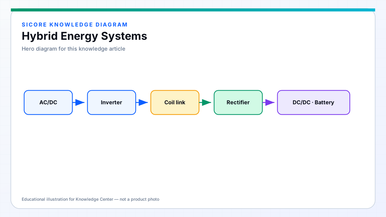
Hybrid energy systems pair a high-energy lithium battery with a high-power auxiliary source — typically supercapacitors ( ultracapacitors ) or a smaller high-power battery segment — managed by a central DC bus controller. The battery supplies steady-state cruise energy; the auxiliary source absorbs regenerative peaks and delivers burst power for acceleration and lift without stressing cells.
Wireless opportunity charging replenishes the battery between missions while the auxiliary buffer handles transient power swings that would otherwise trigger BMS current limits or voltage sag during simultaneous drive and charge.
01Architecture patterns
- Passive parallel: battery and supercapacitor bank on shared DC bus with diode or ORing — simple, less control flexibility.
- Active split: bidirectional DC-DC converters route power between battery, supercapacitor, and load/charger.
- Battery + supercapacitor with wireless receiver on bus: receiver feeds bus; controller allocates charge to battery vs capacitor.
- Dual chemistry: LFP for energy plus small LTO segment for power — rare but avoids separate capacitor maintenance.
02Benefits for wireless-charged fleets
Supercapacitors accept high charge and discharge current with minimal heat — ideal for capturing regenerative braking energy during deceleration into a wireless pad approach. The battery receives smoother average charge current from the wireless receiver rather than alternating charge and regen spikes on a single pack.
Peak power demand on the wireless link drops when the capacitor supplies acceleration surge: a 5 kW average charge with 15 kW peak motor load becomes manageable if the capacitor covers the 10 kW delta for seconds.
03Design and maintenance trade-offs
Hybrid systems add cost, volume, control complexity, and additional failure modes — capacitor ESR drift, voltage balancing across series caps, DC-DC converter efficiency. Justify hybrid architecture when mission profile shows repeatable high peak-to-average power ratio or when regenerative energy recovery measurably reduces net charge minutes. SiCore bus-level charge integration coordinates wireless power with hybrid controllers via standard CAN energy setpoints.