
Artículo wiki · Colección 02
División de Frecuencia
Referencia técnica sobre División de Frecuencia para el diseño, integración e implementación de sistemas de energía inalámbrica.
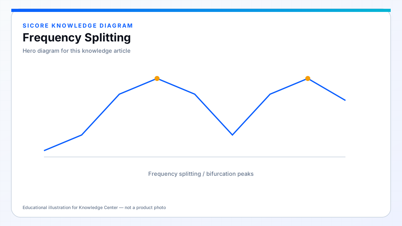
When coupling is strong and Q is high, a resonant link can show frequency splitting (bifurcation): the power or gain curve develops two peaks instead of one. Operating between peaks or jumping between branches can cause sudden power swings, loss of ZVS, or over-voltage on capacitors.
01When splitting appears
- High k (tight gap, good alignment) combined with high Q tanks.
- Certain SS and related compensations are well-known for bifurcation regions.
- Load resistance moves the system across critical coupling boundaries.
02Mitigations
Designers may lower Q, choose LCC-like networks with flatter gain, limit the maximum k mechanically (spacer, coil design), or constrain the control frequency sweep so the inverter never parks on an unstable branch. Characterization must include the best-alignment case — not only the worst — because splitting is often a tight-coupling problem.