
Artículo wiki · Colección 01
Fundamentos de Conversión de Energía
Referencia técnica sobre Fundamentos de Conversión de Energía para el diseño, integración e implementación de sistemas de energía inalámbrica.
6 minArtículo 14/16Fundamentos
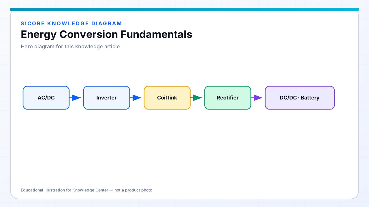
A wireless charger is a chain of power converters. Understanding each stage clarifies efficiency maps, heat sinks, and why “wireless” loss is only one part of wall-to-battery performance.
01Typical stage stack
- Front-end: PFC and AC/DC (mains-powered docks) or DC input from a facility bus.
- Inverter / power stage: creates the high-frequency coil drive.
- Magnetic (or capacitive) link: the wireless gap.
- Receiver rectifier: often synchronous for higher efficiency.
- DC/DC or charger IC: finishes CC/CV battery charging or load regulation.
02Loss buckets
Conduction loss (I²R), switching loss, core loss in ferrite, copper proximity/skin effect in coils, rectifier drop, and cable/bus distribution all add up. Improving only the coil coupling while ignoring a lossy rectifier rarely hits the target system efficiency. Thermal design must follow the same map: heat appears where loss appears.