
Artículo wiki · Colección 03
Fundamentos de Bobinas
Referencia técnica sobre Fundamentos de Bobinas para el diseño, integración e implementación de sistemas de energía inalámbrica.
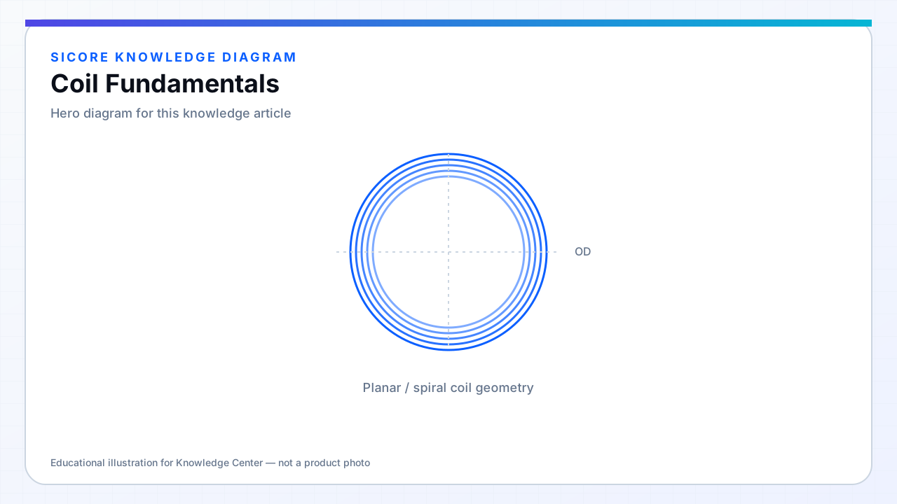
A wireless power coil is an intentional inductor shaped to couple magnetic flux across an air gap. Current in the transmitter winding creates a time-varying magnetic field; the receiver winding intercepts a fraction of that flux and converts it back to voltage. Inductance L, mutual inductance M, and coupling k = M/√(L1L2) are the quantities that connect geometry to circuit behavior.
For industrial AGV and AMR docks, coil design is not an afterthought to the inverter. The coil sets gap tolerance, alignment sensitivity, leakage to nearby steel, and the reactive energy stored in the tank. A 10 kW dock with poor coil engineering will run hot, detune easily, and fail EMC even if the power stage is excellent.
01What the coil must deliver
- Target inductance and k range across the docking envelope (gap, lateral offset, yaw).
- Acceptable AC resistance at operating frequency — not just DC ohms.
- Controlled leakage flux so chassis, fasteners, and foreign metal do not steal or distort the field.
- Mechanical stability under vibration, thermal expansion, and repeated docking cycles.
02Design flow
Start from power, frequency, gap, and coil footprint allowed by the vehicle and floor pad. Estimate L and k with analytical or FEM tools, then iterate conductor sizing, turns, ferrite, and shielding. Validate with impedance measurements on representative fixtures — not a bare coil on a wooden bench.
03Common mistakes
- Specifying only DC resistance or turns count without frequency-dependent loss.
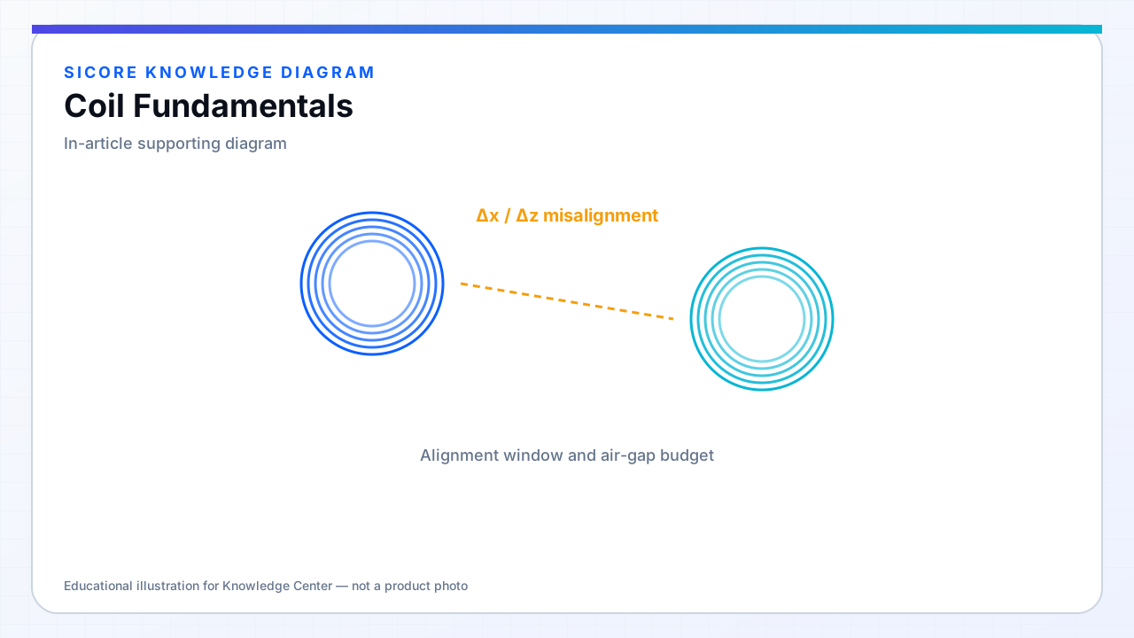
- Optimizing peak k at perfect alignment while the fleet spends most time slightly misaligned.
- Ignoring self-inductance drift when ferrite saturates or heats.
- Treating the receiver and transmitter coils as independent parts instead of a coupled system.