
Artículo wiki · Colección 08
DSP
Referencia técnica sobre DSP para el diseño, integración e implementación de sistemas de energía inalámbrica.
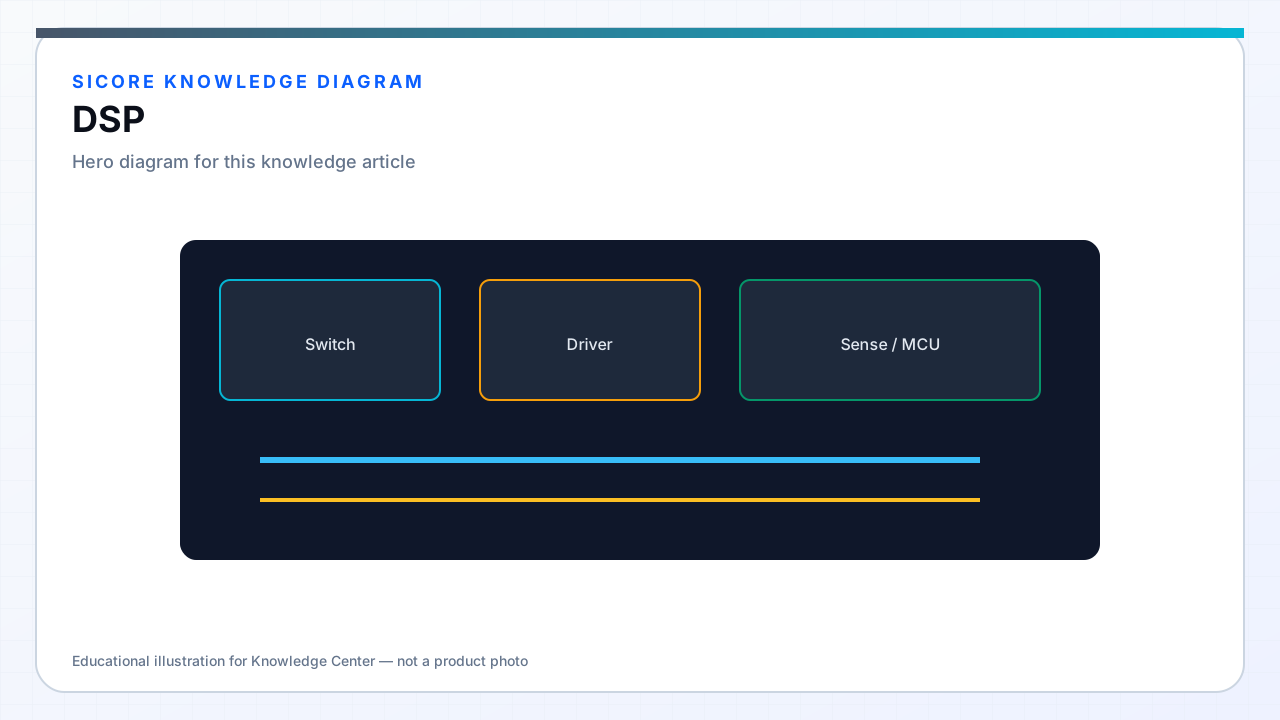
Wireless power transfer at industrial power levels behaves as a resonant, strongly coupled electromagnetic system whose effective load and tuning point shift with alignment, air gap, ferrite temperature, and foreign objects. General-purpose MCUs can execute these algorithms, but DSP cores — or MCUs with integrated MAC units and dual-bank flash — reduce cycle count for the multiply-accumulate heavy workloads that dominate real-time WPT control.
SiCore firmware uses DSP-oriented processing for resonant frequency estimation, impedance phase monitoring, and harmonic content analysis that feeds foreign-object and detuning detection — not for audio or generic filtering alone.
01Typical DSP workloads
- Resonant frequency sweep and phase-difference measurement across primary and secondary sense coils.
- IIR and FIR filtering on high-speed current and voltage samples before protection comparators.
- Clarke/Park or dq-frame transforms when field-oriented control spans multiple phases.
- FFT or Goertzel bins for narrowband interference detection from nearby VFDs or other pads.
- Adaptive tuning: PI or gradient steps on switching frequency or phase shift from impedance estimates.
02Fixed-point vs floating-point
Fixed-point Q15/Q31 math remains common on cost-sensitive receivers where FPU is absent or disabled for deterministic cycle counts. Coefficients are pre-scaled offline; overflow saturation is explicit in every filter stage. Dock controllers at higher power often use Cortex-M4F or M33 with FPU for faster algorithm iteration during commissioning and for model-based impedance solvers that would be fragile in manual fixed-point porting.
SiCore production builds compile with consistent optimization flags and validate bit-exact or bounded-error equivalence between engineering floating-point models and deployed fixed-point implementations before field release.
03Hardware acceleration and partitioning
Where a dedicated DSP (e.g., C2000) coexists with a communication MCU, the split boundary is defined by latency: sub-100 µs protection stays on the power MCU; slower fleet analytics run on the companion. DMA ping-pong buffers feed DSP routines without CPU copy overhead. JTAG or SWD trace during development confirms ISR budgets before locking clock speeds and wait-state configuration.