
Artículo wiki · Colección 10
Puesta a Tierra
Referencia técnica sobre Puesta a Tierra para el diseño, integración e implementación de sistemas de energía inalámbrica.
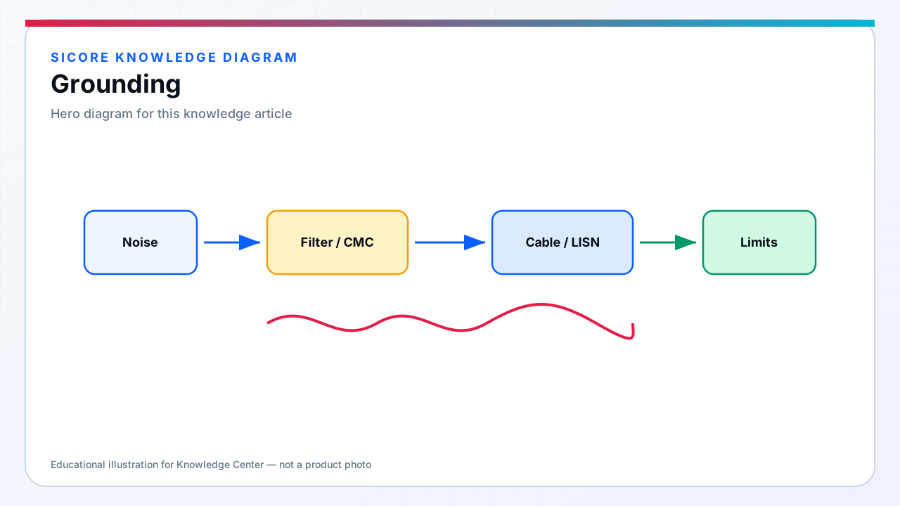
Grounding provides safety fault current return and establishes a reference for electromagnetic compatibility — but conflating the two roles causes chronic EMI problems in industrial installations. SiCore dock designs separate protective earth (PE) for shock protection from functional ground (FG) or signal reference planes on control electronics, bonded at a defined single-point or star location inside the dock controller enclosure. High-frequency inverter return currents must not share long impedance paths with CAN transceiver grounds or NTC sensor returns.
AGV factory floors present non-ideal earth: concrete with rebar mesh, multiple building ground electrodes, and parallel ground paths through steel rack systems and vehicle tires. Multiple floor-flush pads on one aisle can circulate common-mode currents through facility ground when each dock's EMI filter capacitors tie switching noise to PE — site bonding audits are part of SiCore commissioning, not optional field tuning.
01Dock grounding topology
- PE bond: dock frame, pit liner, and AC inlet earth terminal tied to facility grounding conductor per NEC/IEC.
- Internal star point: inverter DC bus return, filter capacitor ground, and control PCB ground plane meet at controlled impedance node.
- Coil shield and ferrite back-plate: bonded to FG with optional Y-capacitor connection to PE through rated components.
- Cable shield termination: 360° clamp at enclosure entry — pigtail grounds are prohibited on SiCore harness drawings.
- Isolation barrier: galvanic separation between mains-side PE and vehicle-side DC reference where battery ground is floating or BMS-defined.
02Common-mode and ground loop mitigation
Common-mode currents from DM-to-CM conversion in inverter filters exit via Y-capacitors to PE — excessive Y-capacitance improves conducted emission but increases ground leakage and touch current, requiring balance against safety standards. Ground loops form when dock signal grounds and vehicle CAN grounds connect through multiple paths: charging cable, steel floor, and wireless comms — differential CAN transceivers tolerate limited CM voltage; beyond ISO 11898 limits, bit errors correlate with charge sessions.
SiCore specifies CAN grounding for fleet integration: single-point chassis bond on receiver, isolated transceiver where customer architecture demands, and maximum harness length from inverter noise sources. Ground potential rise during nearby VFD or welder events can elevate entire floor reference — immunity design assumes CM choke and filter margin, not zero-volt ground.
03Site commissioning and measurement
Commissioning checklists verify PE continuity from each pad to building ground electrode, document ground rod and rebar coupling where known, and measure AC outlet ground impedance. Multi-pad sites record pad-to-pad ground potential difference with all pads at full power — unexpected millivolt-to-volt differences indicate parallel paths requiring bonding strap addition or filter revision. Grounding drawings update when facility electricians add outlets or move subpanels — EMC regression is triggered by infrastructure change, not only product change.