
Artículo wiki · Colección 04
Rectificación Sincrónica
Referencia técnica sobre Rectificación Sincrónica para el diseño, integración e implementación de sistemas de energía inalámbrica.
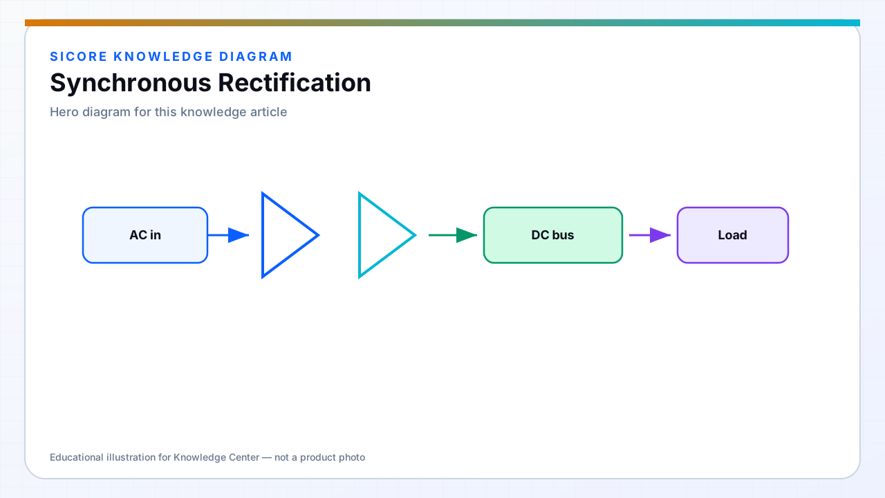
Synchronous rectification (SR) uses low-resistance MOSFETs switched in place of diodes. At the tens-of-ampere currents common in AGV wireless charging, diode forward drop can represent a meaningful fraction of total loss. SR recovers that margin — if gate drive, timing, and layout are correct.
SR is standard on high-power receiver boards but adds complexity: body-diode conduction during dead time, reverse current risk, and sensitivity to tank current zero-crossing detection.
01Implementation essentials
- Accurate current polarity or timing reference from the resonant waveform.
- Gate drive strength and layout to minimize turn-on delay and shoot-through with adjacent legs.
- MOSFET selection with adequate SOA for startup and misalignment peaks.
02Control modes
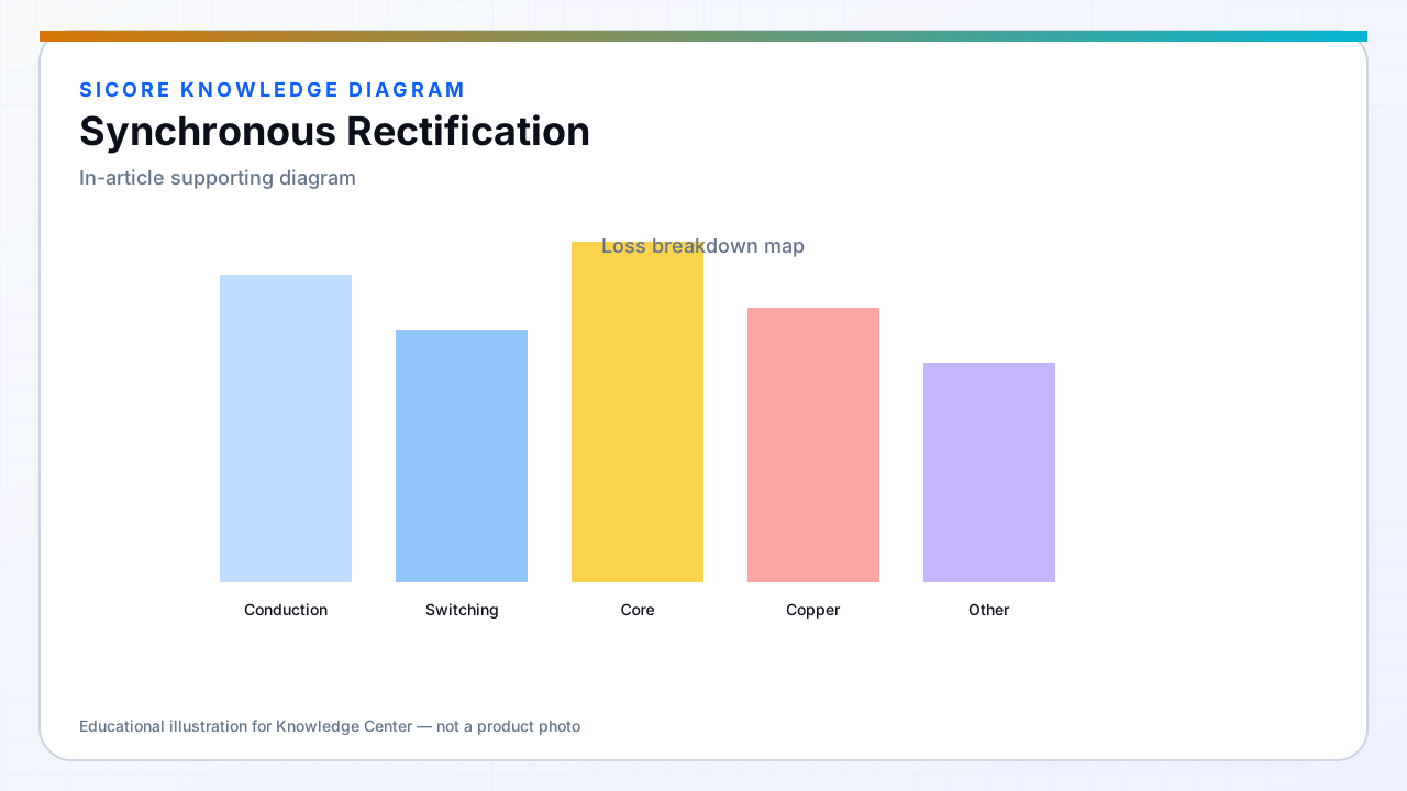
Self-driven SR from auxiliary windings works in some topologies but is less common in tightly controlled industrial receivers. MCU or dedicated SR controllers with ADC or comparator-based zero-cross detection dominate. Always validate SR timing across the full coupling and load range — a few degrees of phase error erases SR benefit.
03Failure modes to test
- Reverse conduction if SR turns on late or off early.
- Excessive ringing on SR switch node from parasitic inductance.
- Thermal hot spots when one leg carries more current due to layout asymmetry.