
Artículo wiki · Colección 09
Monitoreo de Temperatura
Referencia técnica sobre Monitoreo de Temperatura para el diseño, integración e implementación de sistemas de energía inalámbrica.
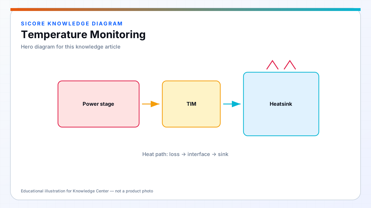
Temperature monitoring closes the loop between thermal design and operational safety: firmware cannot derate or shut down on thermal fault without sensors placed at representative hotspots and sampled with enough bandwidth to catch rate-of-rise events during FOD or misalignment. SiCore platforms monitor FET heatsink, ferrite core or winding proxy, ambient enclosure, and receiver DC output stage — each channel feeds distinct protection and diagnostics behavior.
Sensor data also feeds fleet analytics: rising ferrite baseline across a pad fleet signals mechanical wear or coil damage before hard fault; gradual receiver overtemperature trend flags clogged chassis vents on specific AMR units.
01Sensor types and placement
- NTC thermistors on FET heatsink near device centerline — fast enough for derating, coupled to case temperature.
- Digital I²C/SPI sensors (e.g., TMP117 class) on enclosure air and receiver PCB for accurate absolute telemetry.
- Ferrite or coil winding proxy: NTC embedded in bobbin or bonded to core back with thermal epoxy.
- Isolated temperature sense on high-voltage side via optically or inductively coupled monitors where required.
- Redundant sensors on high-power docks: dual NTC with voting logic for safety-rated shutdown paths.
02Sampling, filtering, and firmware integration
Thermal ADC channels run at 10–100 Hz effective update — faster than energy telemetry, slower than current loops. Median or IIR filtering rejects electrical noise pickup on long NTC leads routed near switching nodes. Rate-of-rise detectors flag abnormal dT/dt during foreign object heating when absolute temperature still below latch threshold.
SiCore derating curves map sensor reading to allowed power setpoint with hysteresis to prevent oscillation at threshold boundary. Ambient-compensated limits adjust maximum coil current when enclosure air sensor reads elevated summer baseline — static absolute thresholds alone cause unnecessary summer derating or winter overconfidence.
03Calibration and fleet visibility
Factory calibration records NTC beta tolerance batch and optional single-point offset correction in NVM. Field service compares live readings to IR spot check during annual pad inspection. CAN and fleet gateway telemetry expose max temperature per session, time above derating threshold, and sensor fault codes — enabling predictive maintenance before customer-visible charge rate reduction.