
Wiki article · Collection 06
Automatic Alignment
Engineering reference on Automatic Alignment for wireless power system design, integration, and deployment.
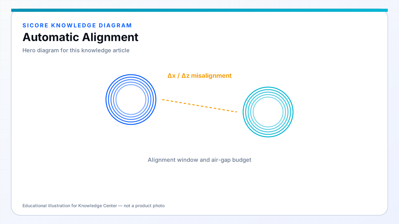
Automatic alignment uses real-time feedback to drive the vehicle into optimal coupling pose after coarse navigation completes. The goal is repeatable high k within the seconds allocated to dock dwell — every centimeter of residual offset directly reduces charge rate or forces the power controller to derate.
SiCore automatic alignment can run on-vehicle — using the robot's drive system — or cooperate with pad-side actuators in fixed-station designs where the vehicle cannot micro-move reliably.
01Alignment signals
- Mutual inductance or reflected impedance asymmetry indicating lateral offset direction.
- Dual-coil or tri-coil pad excitation patterns that triangulate receiver position.
- Ultrasonic or laser range to pad reference features on the vehicle approach axis.
- Visual fiducials with known transform to the coil center point.
02Control sequence
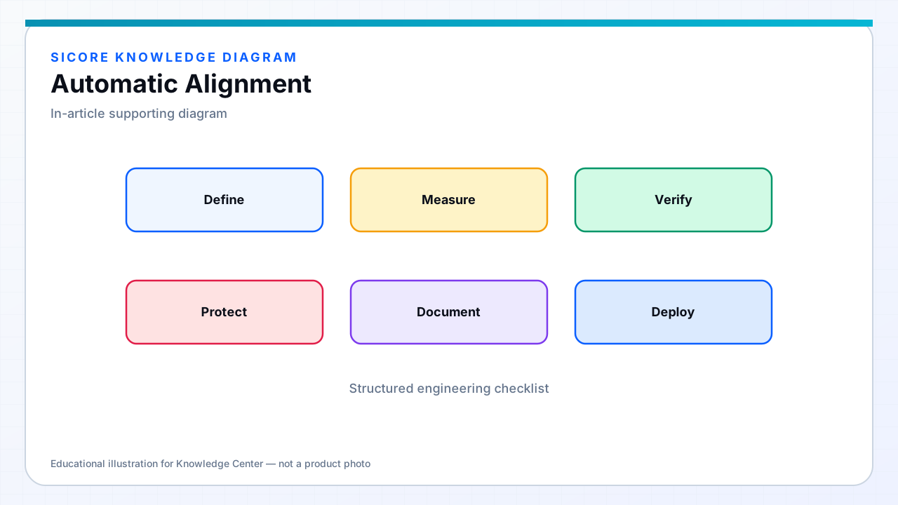
Typical sequence: approach to capture radius → slow-speed alignment mode → iterative correction until alignment score exceeds threshold → hold pose and initiate charge handshake. SiCore alignment thresholds are configurable per vehicle type because receiver height and wheelbase differ across mixed fleets.
03Limits and fallback
Automatic alignment has bounded travel — excessive correction attempts indicate navigation error or mechanical obstruction. After N failed iterations the robot should release, log diagnostics, and reroute rather than block the pad indefinitely. Alignment telemetry distinguishes software tuning issues from worn guides or tire pressure drift.