SiCore Dynamics
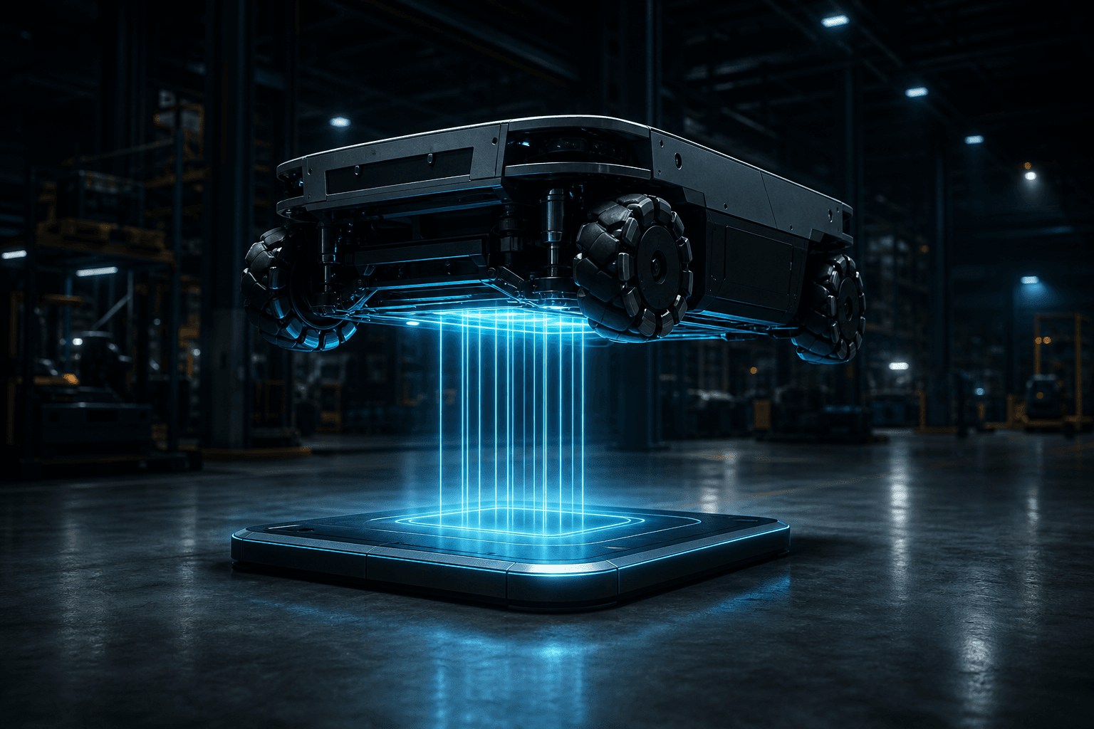
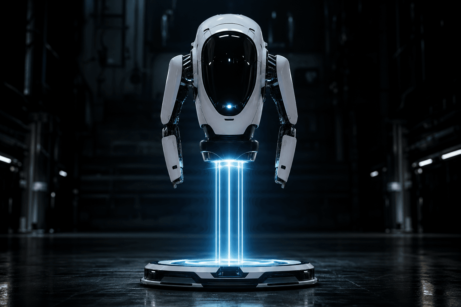
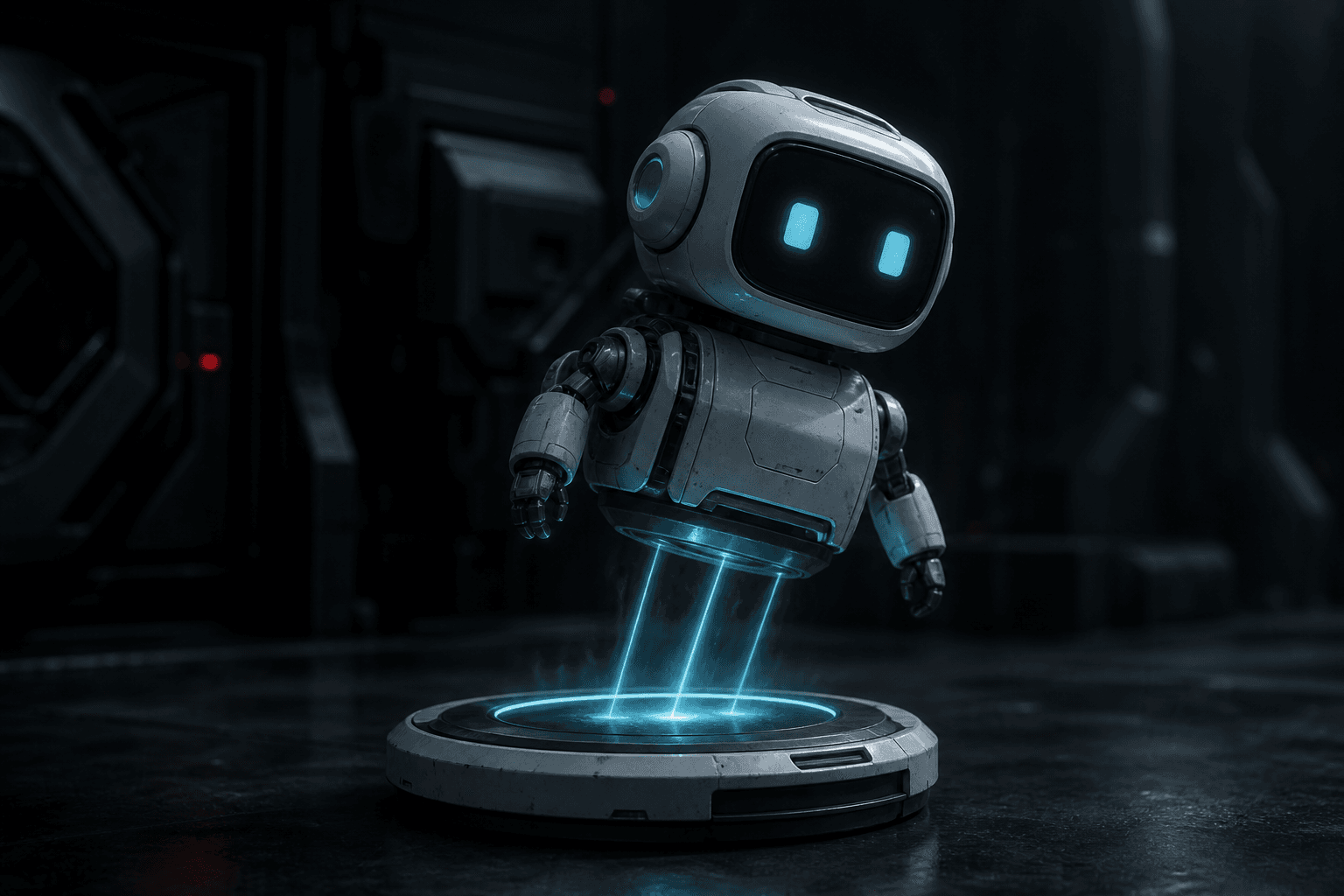
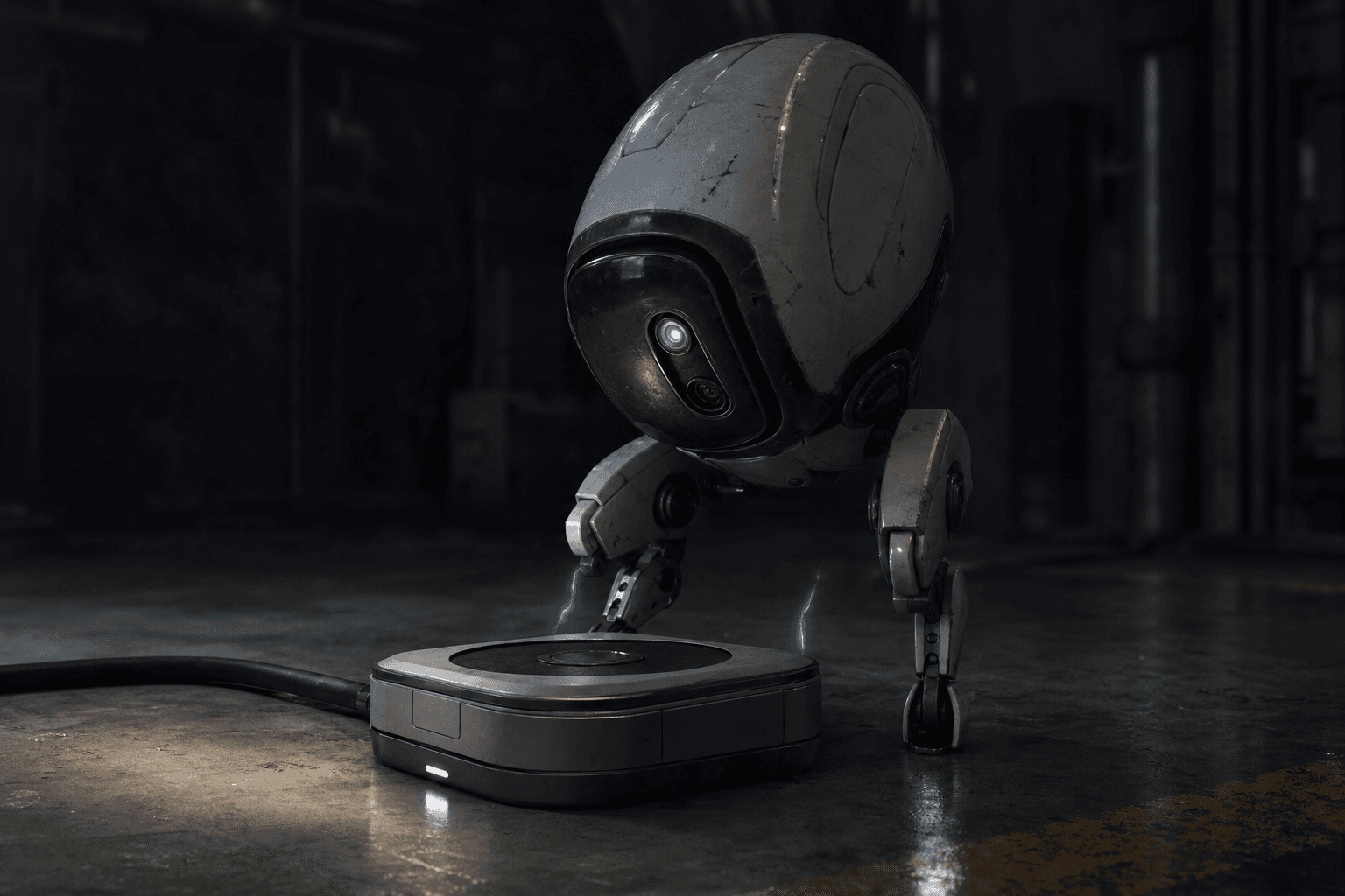
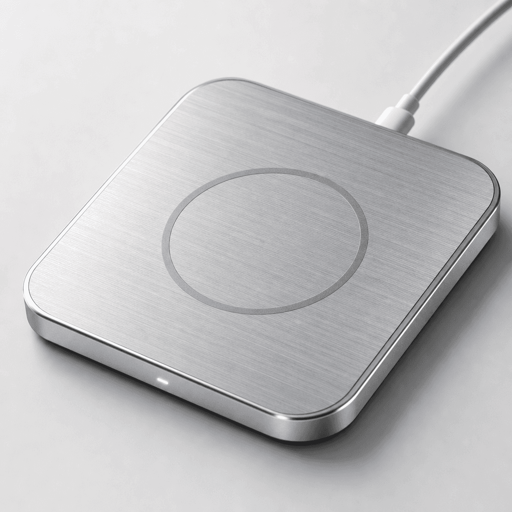
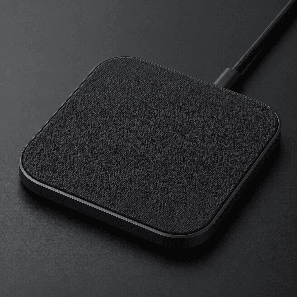
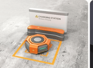
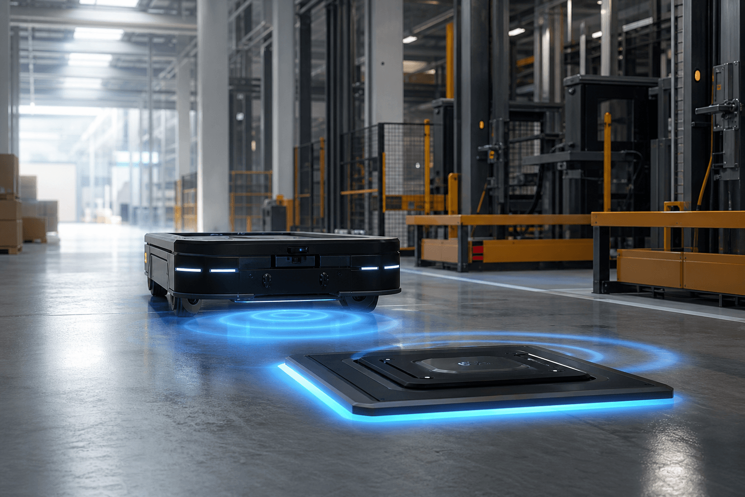
Autonomous robot docking on a wireless charging pad

Plug-Free Docking Technology

Seamless Docking Without Manual Plug-In

SiCore plug-free docking technology enables autonomous machines to charge without cables or manual connectors — through precise docking mechanics, contact or wireless interfaces, position detection, and outdoor-ready reliability.

Dock Mechanics

01

Precision Docking Starts with Mechanical Design

Dock Mechanics defines how a robot physically aligns and secures itself before power transfer begins. A well-designed mechanical interface delivers high repeatability across real industrial environments.

  • High RepeatabilityConsistent docking performance
  • Robust DesignBuilt for industrial environments
  • AutonomousNo human intervention required
  • High ToleranceHandles real-world positioning variation
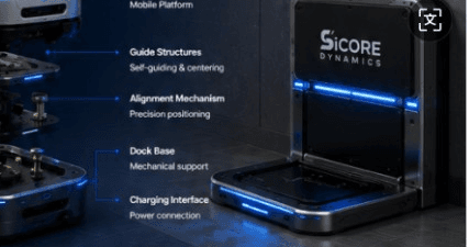
Dock mechanics exploded view with robot, guides, and charging interface

Docking Process Overview

From Approach to Charging

  1. 01

    Approach

    Robot navigates to the docking area

  2. 02

    Self-Guidance

    Mechanical guides steer the robot

  3. 03

    Alignment

    Precision alignment is achieved

  4. 04

    Lock & Secure

    Mechanical lock engages if required

  5. 05

    Power Ready

    Power interface is connected

  6. 06

    Start Charging

    Charging begins automatically

Implementation Methods

How Precision Docking Is Achieved

01

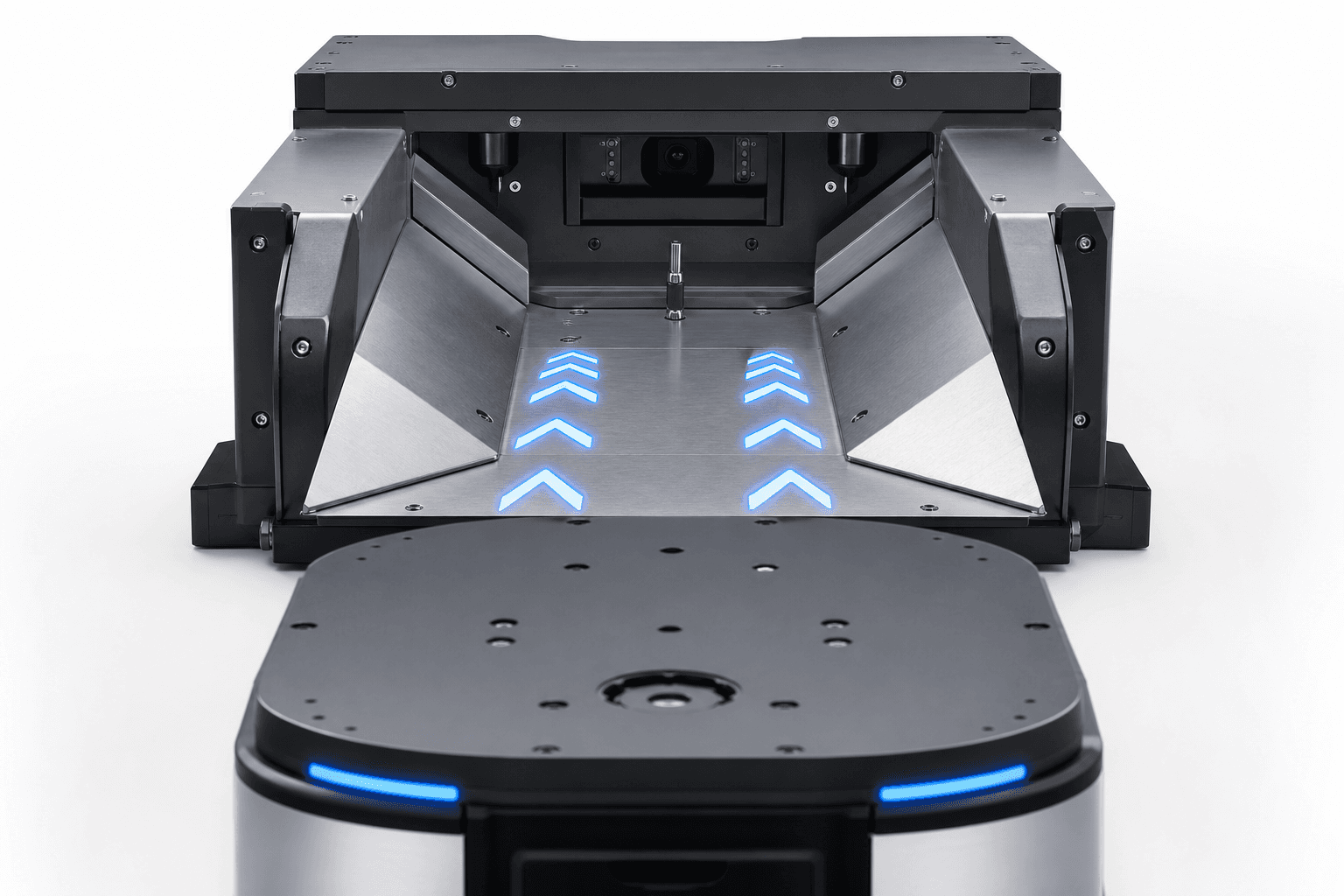
Self-Guiding

Passive mechanical features correct the robot’s trajectory as it enters the dock, enabling smooth docking with large entry tolerance.

Learn more

Common structures

  • Funnel Guide
  • V Guide
  • Chamfer Guide
  • Rail Guide

Key benefits

  • Passive guidance
  • Large tolerance
  • Smooth entry
  • No active control required
02

Self-Centering

Centering mechanisms bring the robot to the exact docking center, compensating for X/Y offset and improving power interface alignment.

Learn more

Common structures

  • Cone Guide
  • Pin & Hole
  • Pin & Slot
  • Magnetic Centering

Key benefits

  • High centering accuracy
  • Compensates X/Y offset
  • Improves power transfer
  • Reduces wear

03

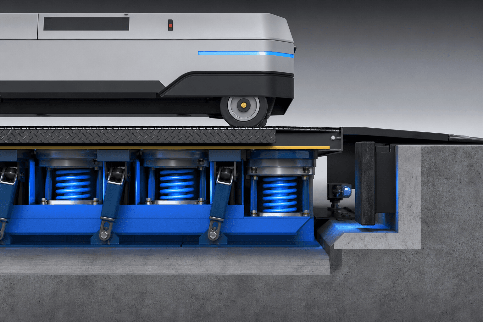
Compliance & Compensation

Compliance mechanisms absorb impact and compensate for height or parallelism errors, protecting both the dock and the vehicle.

Learn more

Common structures

  • Floating Dock
  • Spring Compensation
  • Passive Compliance
  • Shock Absorption

Key benefits

  • Absorbs impact energy
  • Tolerates height variation
  • Protects mechanical parts
  • Improves reliability

04

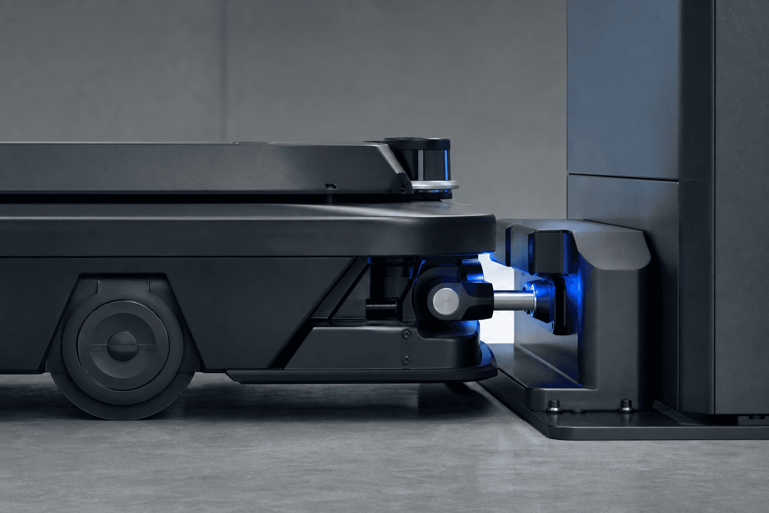
Locking Mechanism

Locking holds the robot securely during charging or in harsh environments, preventing disengagement caused by vibration or external force.

Learn more

Common structures

  • Pin Lock
  • Hook Lock
  • Magnetic Lock
  • Electromagnetic Lock

Key benefits

  • Secure during operation
  • Resists vibration
  • Prevents disengagement
  • Supports harsh environments

05

Tolerance Optimization

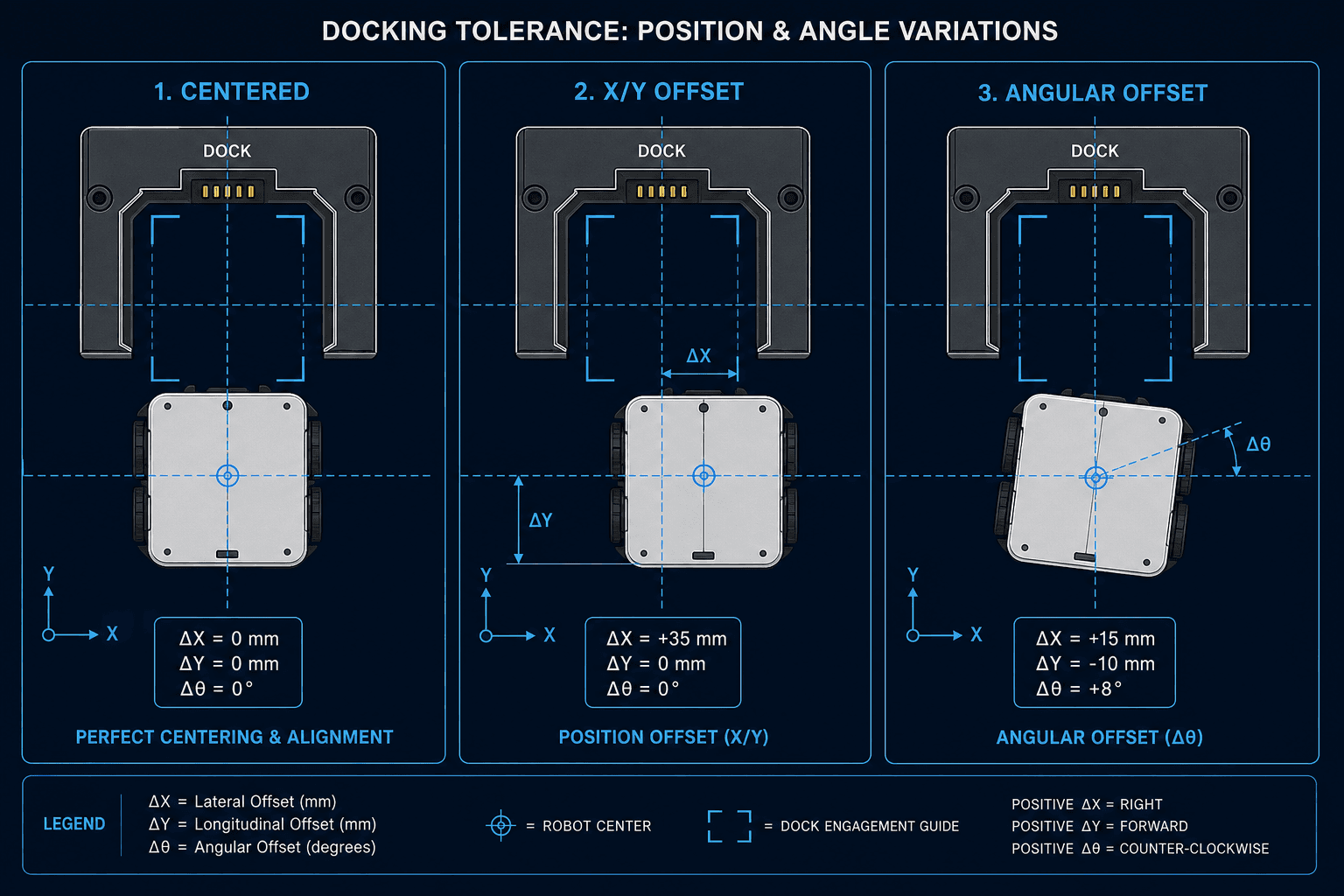
Dock geometry and clearance are optimized so docking remains consistent under centered, offset, angular, wear, and thermal-expansion conditions.

Learn more

Common structures

  • Dock Geometry
  • Guide Symmetry
  • Clearance Design
  • Wear Allowance
  • Thermal Expansion

Key benefits

  • Handles real-world variation
  • Consistent performance
  • Long-term repeatability
  • Reduced maintenance
Contact Dock

02

Direct Electrical Connection Without Plugging In

Contact docks deliver power through conductive interfaces that engage automatically when the machine docks. This approach supports high power transfer with a simple, production-ready connection path for many industrial platforms.

  • Automatic EngagementNo manual plug-in required
  • High Power PathSupports demanding charge rates
  • Wear ResistantBuilt for repeated dock cycles
  • Production ReadySimple, scalable interface design
Contact dock conductive interface engaging automatically

Contact Charging Process

From Dock Presence to Power Flow

  1. 01

    Approach

    Machine enters the contact dock zone

  2. 02

    Align

    Mechanical guides bring contacts into position

  3. 03

    Engage

    Conductive interfaces make solid contact

  4. 04

    Verify

    Presence and polarity checks confirm readiness

  5. 05

    Charge

    High-current power transfer begins

  6. 06

    Release

    Contacts disengage cleanly on departure

Contact Dock Implementation Methods

How Reliable Contact Power Is Achieved

01

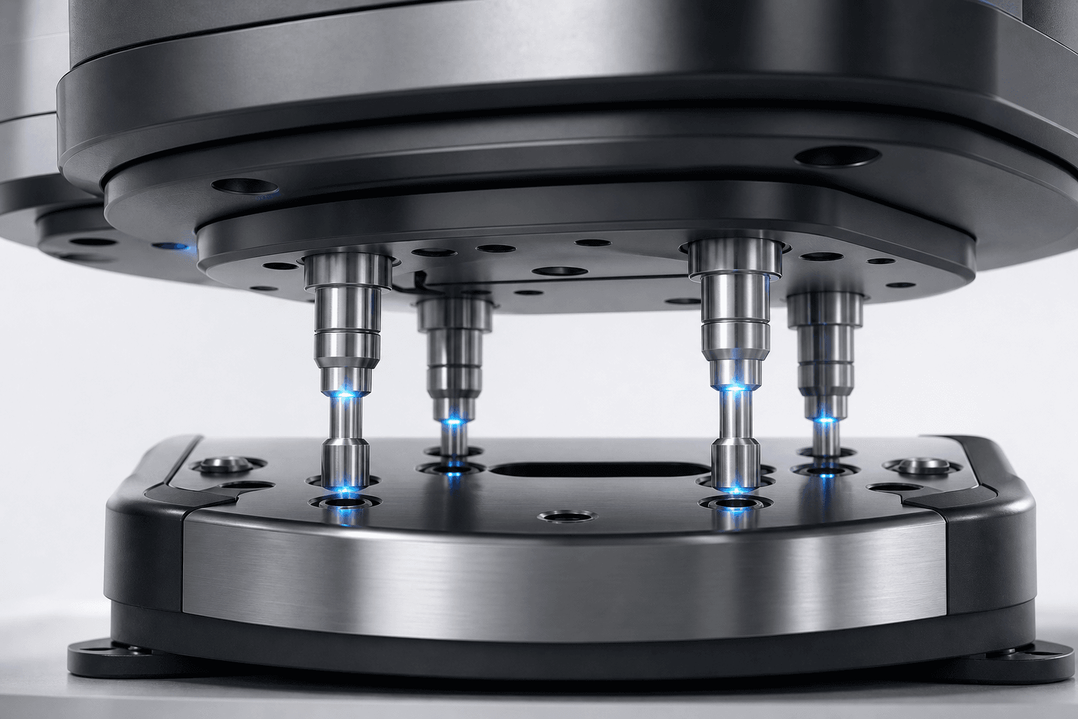
Spring-Loaded Pins

Pogo-style or spring pins maintain consistent contact force across height variation, ensuring a stable electrical path through every docking cycle.

Learn more
Spring-loaded contact pins engaging a docking plate

Common Structures

  • Pogo Pins
  • Spring Array
  • Pin Carrier
  • Contact Cap

Key Benefits

  • Consistent contact force
  • Tolerates height variation
  • High cycle durability
  • Easy module replacement

02

Conductive Pads

Flat pad interfaces create a broad conductive area for power transfer, simplifying alignment and supporting robust current delivery at fixed stations.

Learn more
Conductive pad contact interface on a docking station

Common Structures

  • Pad Plate
  • Dual Pad
  • Rail Pad
  • Sealed Pad

Key Benefits

  • Large contact area
  • High current capability
  • Simple geometry
  • Suitable for fixed docks

03

Brush Contacts

Brush interfaces maintain electrical continuity during small relative motion, absorbing vibration and minor misalignment after the machine settles.

Learn more
Brush contact modules for vibration-tolerant power transfer

Common Structures

  • Carbon Brush
  • Brush Block
  • Spring Brush
  • Wipe Path

Key Benefits

  • Tolerates micro-motion
  • Stable under vibration
  • Self-cleaning wipe action
  • Industrial proven form

04

Wear & Protection Design

Contact materials, plating, and sealing are selected to resist oxidation, abrasion, and contamination so the interface stays reliable over long duty cycles.

Learn more
Protected contact interface designed for long duty cycles

Common Structures

  • Hard Plating
  • Wipe Seal
  • Dust Cover
  • Replaceable Tip

Key Benefits

  • Longer contact life
  • Resists contamination
  • Lower maintenance
  • Stable resistance over time

05

High-Current Path Optimization

Bus geometry, parallel paths, and thermal design are optimized so contact docks deliver high power safely with low loss and controlled temperature rise.

Learn more
Diagram of high-current contact path and thermal considerations
  • Nominal Contact

    Full pad engagement

  • Partial Offset

    Reduced overlap margin

  • Thermal Rise

    Managed under load

Common Optimization Factors

  • Bus Geometry
  • Parallel Paths
  • Contact Area
  • Thermal Path
  • Sense Feedback

Key Benefits

  • High power transfer
  • Low connection loss
  • Controlled heating
  • Safe charge readiness
Wireless Dock
Wireless dock autonomous contactless charging

Plug-Free Docking Technology

Wireless Dock

Autonomous Contactless Charging

SiCore wireless docking stations combine precise mechanical positioning with contactless power transfer — enabling safe, efficient, and fully autonomous charging without exposed electrical contacts.

01 Dock Architecture

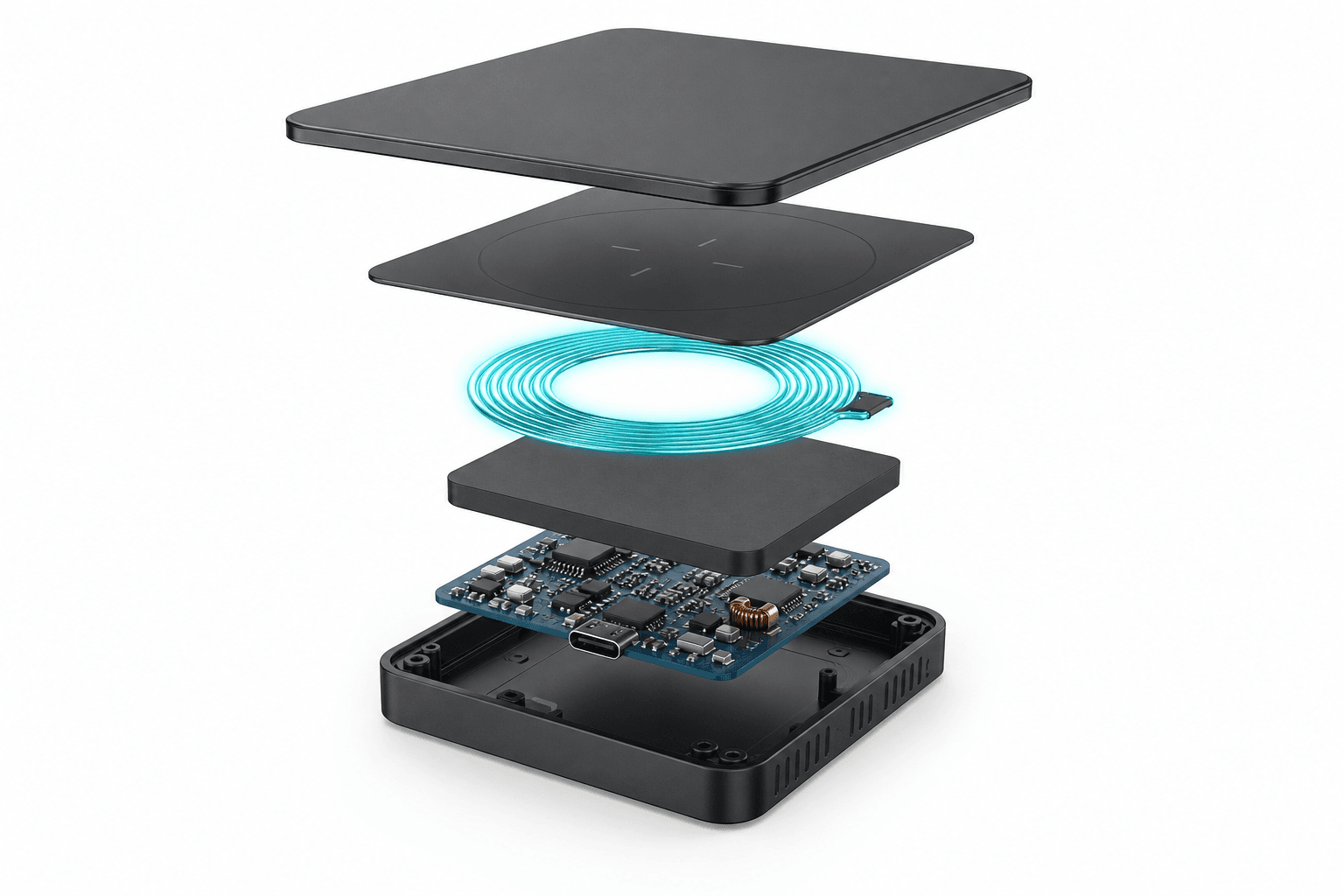
The wireless dock integrates transmitter coils, ferrite structures, power electronics, and a durable charging surface into a compact, serviceable platform.

Learn more
Exploded view of wireless dock layers and internal components
  1. 01Top CoverProtection & aesthetics
  2. 02Charging SurfaceDurable interface
  3. 03Transmitter CoilHigh efficiency power transfer
  4. 04Ferrite StructureMagnetic field control
  5. 05Power ElectronicsIntelligent power management
  6. 06Dock HousingStructural & environmental protection

02 Coil Alignment

Accurate coil alignment ensures maximum coupling efficiency and stable charging performance across real docking stops.

Learn more
  • Alignment Window (X / Y)

    ±20 mm

  • Typical Efficiency

    90%+ within window

  • Perfect Alignment01

    Perfect Alignment

    Optimal coupling, highest efficiency.

  • Small Offset02

    Small Offset

    Slight efficiency reduction, still within alignment window.

  • Large Offset03

    Large Offset

    Charging may be limited or not allowed.

03 Charging Surface

The charging surface is engineered for mechanical durability, wear resistance, and safe everyday operation in industrial environments.
Learn more
  • Wear Resistant

    > 100,000 docking cycles

  • High Load Capacity

    Supports heavy robots and equipment

  • Easy to Clean

    Smooth surface, resists dirt and oil

  • Anti-Slip Design

    Secure docking in all conditions

  • Aluminum Surface

    Aluminum Surface

    High strength, excellent heat dissipation

  • Composite Surface

    Composite Surface

    Lightweight, corrosion resistant

  • Rubber Surface

    Rubber Surface

    Anti-slip, vibration dampening

04 Foreign Object Protection

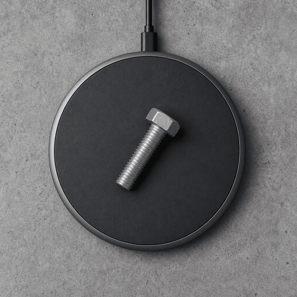
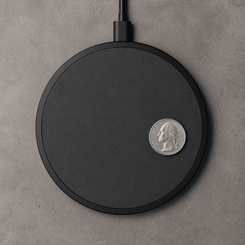
Advanced FOD technology monitors the charging area for metallic objects and disables charging when a hazard is detected.
Learn more
  • Bolt DetectedBlocked

    Bolt Detected

    Charging disabled

  • Key DetectedBlocked

    Key Detected

    Charging disabled

  • Coin DetectedBlocked

    Coin Detected

    Charging disabled

  • No ObjectClear

    No Object

    Charging enabled

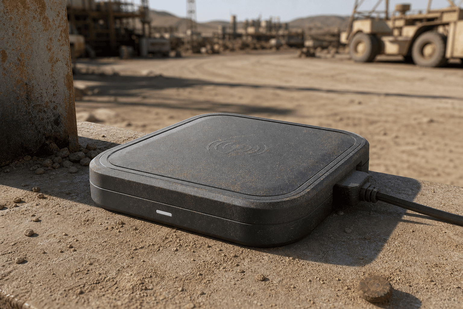
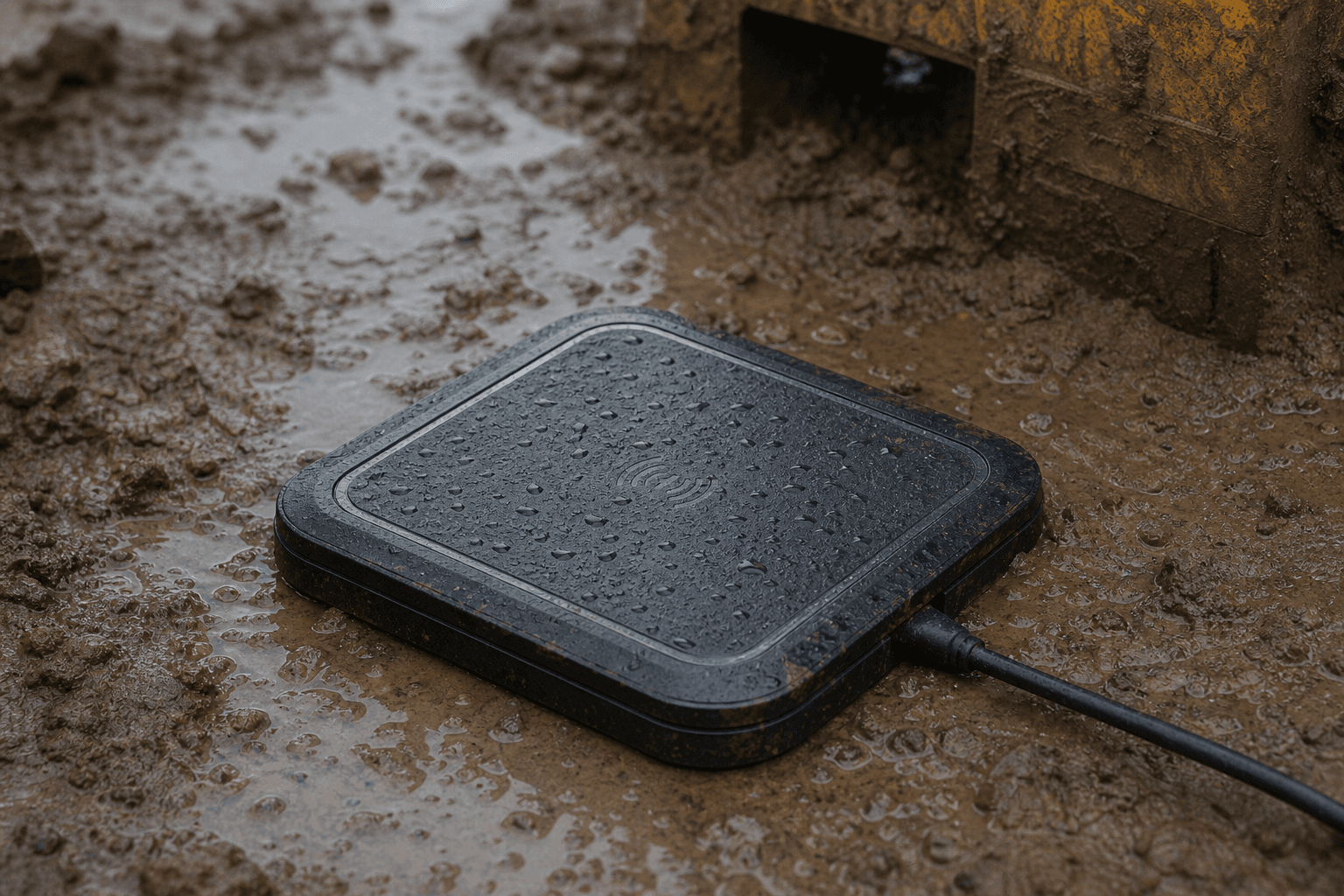
05 Sealed Dock Design

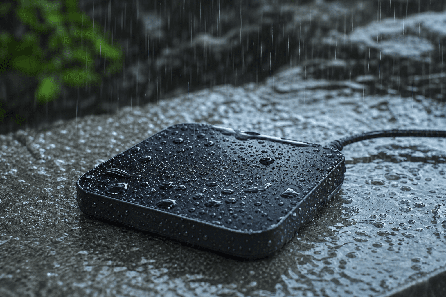
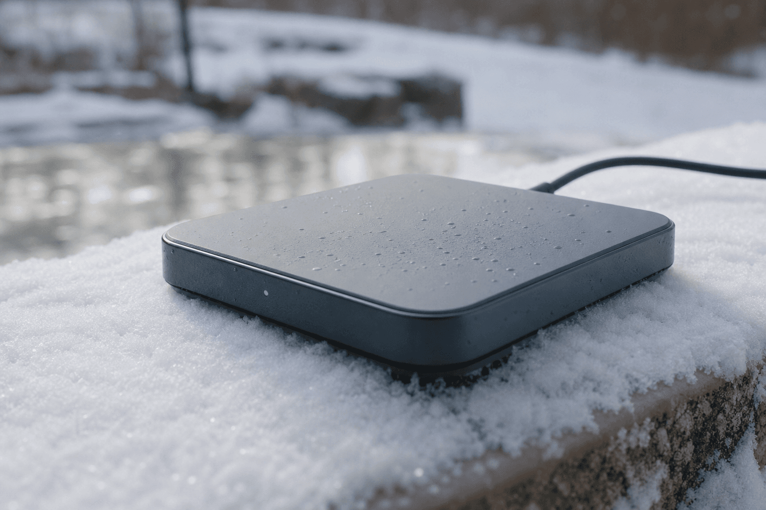
A fully sealed dock withstands water, dust, chemicals, and extreme weather for reliable outdoor and industrial deployment.

Learn more
  • IP67 Protection

    Waterproof and dustproof

  • Corrosion Resistance

    Long-term material durability

  • Chemical Resistant

    Handles washdown and fluids

  • Impact Resistant

    Built for industrial duty

  • Rain environment

    Rain

  • Snow environment

    Snow

  • Dust environment

    Dust

  • Mud environment

    Mud

Reliable Connection. Continuous Power.

SiCore Wireless Dock delivers safe, efficient, and autonomous charging for the next generation of intelligent machines.

Contact Our Engineers
Position Detection

04

Know When Alignment Is Ready for Charging

Position detection confirms that the machine is correctly aligned before charging begins. Sensing and feedback help validate docking accuracy, improve safety, and ensure efficient power transfer at every stop.

  • Dock PresenceConfirm station before approach
  • Alignment ReadyValidate pose before charging
  • Misalignment FeedbackCorrect approach in real time
  • Autonomous RoutinesSupport full dock sequences
Position detection guiding autonomous docking alignment

Detection Methods

How Position Is Sensed Before Charging

01

Vision Guidance

Autonomous robots first identify the docking station using onboard vision systems before entering the final docking process. Cameras continuously detect visual features such as AprilTags, fiducial markers, QR codes, or natural structural features to estimate the dock's position and orientation. Compared with traditional fixed-position docking, vision guidance enables greater flexibility and allows docking stations to be relocated without extensive mechanical adjustments.

Modern AI vision algorithms further improve robustness under varying lighting conditions and partially occluded environments, making vision-based docking an essential technology for next-generation autonomous machines.

Learn more

Core Technologies

  • AprilTag Detection
  • ArUco Marker Recognition
  • AI Vision Algorithms
  • Feature Matching
  • Pose Estimation

Key Benefits

  • Relocatable docking stations
  • Flexible approach without fixed fixtures
  • Robust under lighting variation
  • Works with partial occlusion
  • Accurate dock pose estimation

02

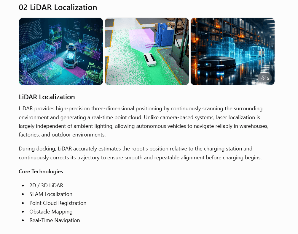
LiDAR Localization

LiDAR provides high-precision three-dimensional positioning by continuously scanning the surrounding environment and generating a real-time point cloud. Unlike camera-based systems, laser localization is largely independent of ambient lighting, allowing autonomous vehicles to navigate reliably in warehouses, factories, and outdoor environments.

During docking, LiDAR accurately estimates the robot's position relative to the charging station and continuously corrects its trajectory to ensure smooth and repeatable alignment before charging begins.

Learn more
LiDAR point-cloud localization for indoor, warehouse, and night-time docking environments

Core Technologies

  • 2D / 3D LiDAR
  • SLAM Localization
  • Point Cloud Registration
  • Obstacle Mapping
  • Real-Time Navigation

Key Benefits

  • Lighting-independent localization
  • High-precision 3D positioning
  • Reliable warehouse and outdoor use
  • Continuous trajectory correction
  • Smooth, repeatable dock alignment

03

Infrared Guidance

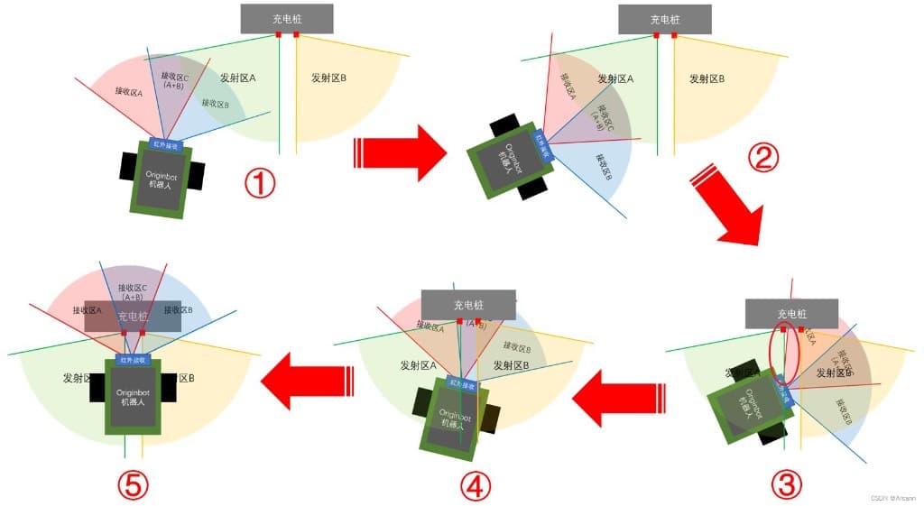
Five-step infrared guidance process from detection to docking
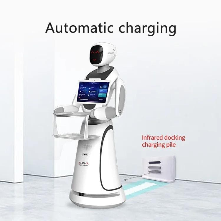
Service robot with infrared docking charging pile for automatic charging
What is Infrared Guidance?

Infrared Guidance uses IR emitters installed on the charging dock and IR receivers mounted on the robot. As the robot approaches the station, it detects the infrared signal and adjusts its trajectory until it reaches the correct docking position.

Advantages
  • Low system cost
  • Simple implementation
  • Fast response
  • Low power consumption
  • Proven and mature technology
Typical Applications
  • Robotic vacuum cleaners
  • Consumer robots
  • Educational robots
  • Indoor delivery robots
  • Small service robots
Learn more

04

Ultrasonic Detection

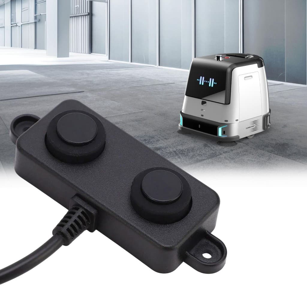
Ultrasonic sensor module used for short-range docking detection
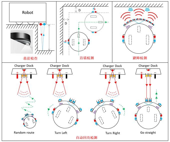
Diagrams of ultrasonic cliff, wall, obstacle, and auto-recharge detection
What is Ultrasonic Detection?

Ultrasonic sensors emit high-frequency sound waves and calculate the distance to nearby objects from the reflected echoes. During docking, these sensors continuously measure the distance between the robot and the charging station to enable smooth, collision-free positioning.

Advantages
  • Accurate short-range detection
  • Low cost
  • Resistant to lighting changes
  • Reliable obstacle detection
  • Ideal as a secondary positioning sensor
Typical Applications
  • AGVs
  • Cleaning robots
  • Mobile service robots
  • Smart warehouse vehicles
  • Indoor automation equipment
Learn more
Outdoor Reliability

05

Built for Real Environments, Not Lab Conditions

Outdoor reliability ensures docking continues to work under dust, moisture, temperature variation, and vibration. Materials, sealing, and interface design are selected for long-term operation in demanding field conditions.

Reliability Pillars

How Outdoor Docking Stays Dependable

01

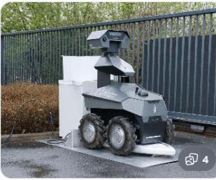
Weather Protection

Sealed outdoor equipment operating in heavy rain at night
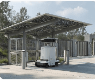
Autonomous robot docked under a solar-panel shelter outdoors
Rugged outdoor robot at a weather-exposed docking station

Designed to operate reliably in rain, dust, and outdoor environments with sealed enclosure protection.

Learn more

Core Technologies

  • IP67 / IP69K
  • Waterproof Sealing
  • Dust Protection

02

Corrosion Resistance

Coastal outdoor furniture and charging interface near the beach
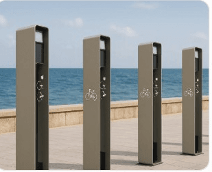
Corrosion-resistant outdoor charging bollards along a seaside promenade
Protected outdoor charging station beside a garden bench

Durable materials and protective coatings extend product life in humid and corrosive environments.

Learn more

Core Technologies

  • Anodized Aluminum
  • Protective Coating
  • Stainless Steel Hardware

03

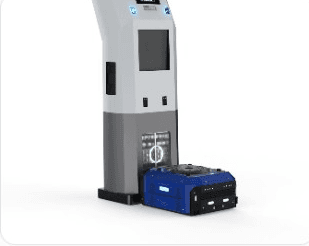
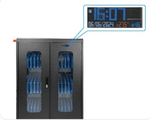
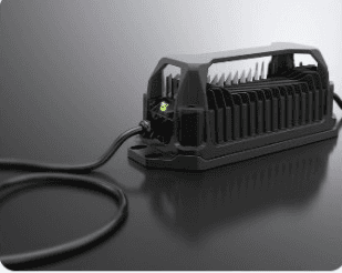
Thermal Management

Mobile robot docking at a tall outdoor charging pillar
Industrial cabinet with temperature and humidity monitoring display
Power electronics module with metal heatsink for thermal dissipation

Stable operation across high and low temperatures through optimized thermal design.

Learn more

Core Technologies

  • Heat Dissipation
  • UV Resistance
  • Wide Temperature Operation

04

Mechanical Durability

Hexagonal robot docking at a marked outdoor charging station
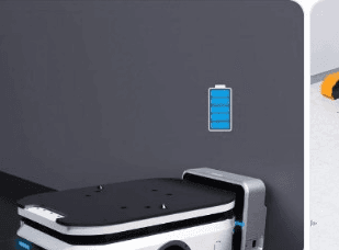
Robot docked at a wall charging port with battery status indicator
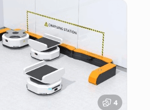
Multiple robots charging in a protected docking bay

Engineered to withstand repeated docking cycles, vibration, and accidental impacts.

Learn more

Core Technologies

  • Shock Resistance
  • Vibration Resistance
  • Structural Strength