
Wiki article · Collection 10
Filtering
Engineering reference on Filtering for wireless power system design, integration, and deployment.
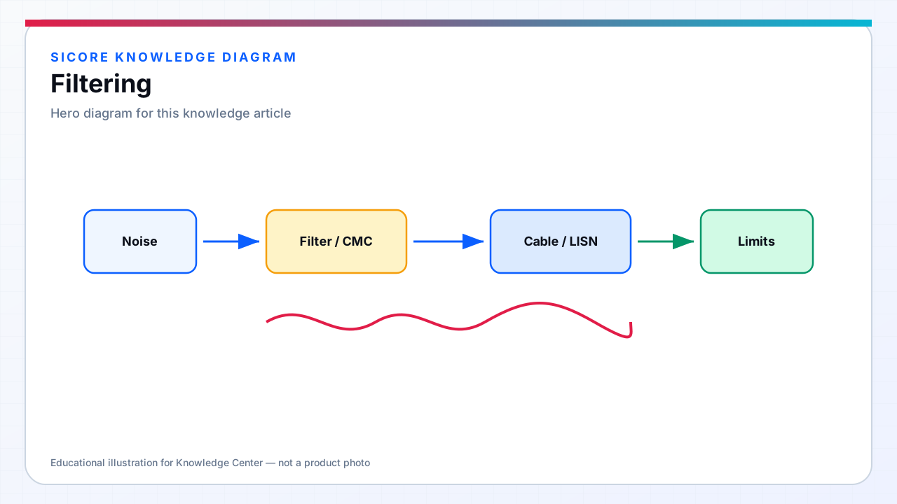
EMI filters attenuate unwanted frequency components before they propagate on conductors or excite radiating structures. SiCore dock inverters require AC mains filters sized for continuous multi-kilowatt input current with low insertion loss at 50/60 Hz and high attenuation above 150 kHz — the overlap between WPT fundamental and CISPR measurement bands demands careful filter design to avoid resonant peaks. Receiver-side DC filters suppress rectifier switching harmonics on the battery connection that otherwise radiate from vehicle harnesses and disturb BMS sense lines.
Filter effectiveness depends on source impedance, load impedance, and placement relative to noise generation. Filters mounted at the AC inlet attenuate inverter noise before facility wiring acts as an antenna; filters placed incorrectly — after long internal leads — allow the enclosure interior to radiate despite compliant inlet measurement.
01Filter component roles
- Common-mode chokes: high CM impedance on L and N (or + and −) together — primary tool for mains and DC bus CM noise.
- X-capacitors (DM): across line conductors — attenuate differential noise; must be safety-rated and discharge-controlled.
- Y-capacitors (CM): line to ground — provide CM return path; limited by leakage current regulations.
- Feed-through capacitors: bulkhead-mounted for shielded cable entries on dock comms and safety IO.
- Ferrite beads and CM slugs: supplemental HF suppression on gate-driver supplies and CAN lines — not substitutes for power-line filters.
02Dock and receiver filter architecture
SiCore dock AC filter stages integrate with PFC and inrush limiting — choke saturation at peak input current must not occur during soft-start or post-fault reclosure. Multi-stage LC filters use damped designs to avoid high-Q resonance when interacting with facility power factor correction capacitors on the same branch circuit — a common cause of field emission failures not seen in isolated lab LISN setups.
Receiver DC output filters combine bulk electrolytic for low-frequency ripple and ceramic or film capacitors for MHz switching content from synchronous rectifiers. Layout places filter capacitors immediately adjacent to SR FET terminals with minimal loop area; external filter modules at the battery connector address harness inductance that on-board caps cannot overcome.
03Validation and derating
Filter components operate hot in sealed dock pits — SiCore validates choke temperature rise at 50 °C ambient and maximum duty cycle; derating applies to capacitor RMS ripple current. Filter BOM is locked to compliance reports: substituting 'equivalent' chokes with different leakage inductance or core material shifts attenuation curves and voids certification. Pre-compliance LISN scans document margin per harmonic order, guiding incremental filter optimization before formal CISPR 11 testing.