
Wiki article · Collection 10
Conducted Emission
Engineering reference on Conducted Emission for wireless power system design, integration, and deployment.
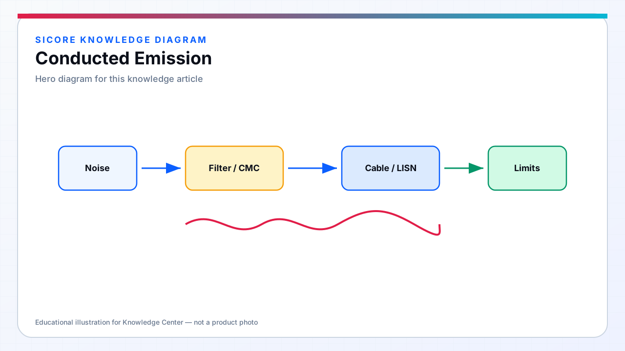
Conducted emission measures RF voltage (or current) present on external power cables — AC mains for dock transmitters and DC supply lines for AGV receivers and control electronics. High-frequency inverters generate switching frequency fundamentals and harmonics that propagate via differential and common-mode paths onto conductors; facility wiring then distributes noise to parallel loads including PLCs, servers, and lighting dimmers. SiCore conducted emission design targets both compliance margins and operational coexistence on shared branch circuits feeding multiple charging pads.
Measurement uses a Line Impedance Stabilization Network (LISN) to present defined source impedance (50 Ω || 50 µH typical for mains) while passing AC or DC power. Results are compared to quasi-peak and average limit lines from CISPR 11 or EN 55011 — peak scans guide debugging; QP/AV determine pass/fail.
01Noise modes and sources
- Differential mode: line-to-neutral (or +/−) noise from inverter switching current in the DC bus loop.
- Common mode: equal-potential noise on both conductors relative to ground — dominates above filter corner without CM choke.
- PFC switching: distinct spectral lines at PFC frequency and harmonics overlapping WPT harmonics.
- Receiver SR switching: MHz content on battery cables radiating from harness if not filtered at source.
- Ground leakage from Y-caps: appears as conducted measurement artifact if LISN ground reference differs from installation.
02Mitigation hierarchy
Source reduction precedes filtering: minimize inverter switching loop area, use soft-switching topologies where efficiency permits, and synchronize or spread spectrum only when regulatory analysis confirms acceptability. AC filter stages sized for continuous current without choke saturation; damper resistors on filter capacitors suppress LC resonance with facility power factor correction.
DC conducted emission on receiver battery ports addresses BMS compatibility — OEM specs often impose stricter limits than generic industrial standards. SiCore places CM chokes on battery output where harness length exceeds 1 m or where customer qualification demands; measurement uses DC LISN or clamp-on current probe methods per OEM test plan.
03Field troubleshooting
Site failures absent in lab often trace to installation variance: shared neutral impedance, missing PE bond, or parallel VFDs on the same subpanel. SiCore field engineers use portable spectrum analyzers with current probes on mains feeds during live charging — correlating spectral lines to inverter modes confirms product vs installation origin. Remediation may be filter retrofit, subpanel dedicated circuit, or facility harmonic mitigation — documented in commissioning closure reports.