
Wiki article · Collection 10
Radiated Emission
Engineering reference on Radiated Emission for wireless power system design, integration, and deployment.
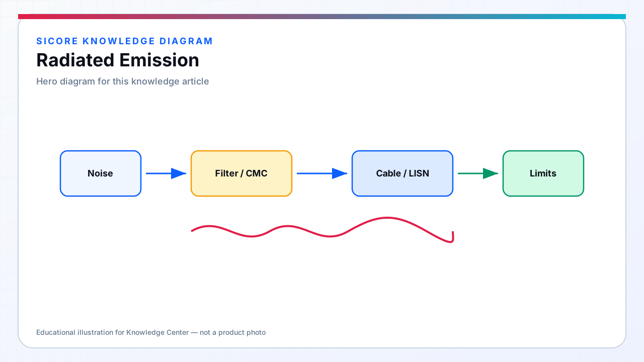
Radiated emission is electromagnetic energy propagating from the product into free space — measured as field strength versus frequency at defined distance with calibrated antennas. SiCore wireless charging systems combine intentional sub-MHz magnetic fields for power transfer with unintentional radiation from switching harmonics, enclosure slot antennas, and cable common-mode currents. Below roughly one wavelength, near-field H-field dominates around coils and high-current loops; above 30 MHz, far-field E-field from apertures and cables typically governs compliance.
Semi-anechoic or open-area test sites measure radiated profiles with the product in worst-case orientation and height per CISPR 11. Floor-flush docks require representative installation fixtures — pit mockup, steel plate simulation, and cable exit routing matching field deployment — because radiated patterns differ from benchtop inverter boards alone.
01Dominant radiating structures
- Coil windings and tank capacitors: strong H-field at WPT frequency; harmonics extend into measured bands.
- Enclosure seams and vents: slot antennas when internal DM noise drives asymmetric currents on exterior surfaces.
- Unfiltered cable harnesses: CM current radiates efficiently — 'long wire' emission from CAN and mains pigtails.
- Gate-driver and PFC loops: cm-scale loops radiate MHz harmonics when return path is discontinuous.
- Receiver belly pan openings: compromised shield integrity radiates SR switching noise upward into vehicle electronics zone.
02Control techniques
Layout minimizes high di/dt loop area and places switching nodes on inner PCB layers where feasible. Shielding cans, conductive gaskets, and filtered feed-throughs address enclosure leakage. Ferrite clamps and CM chokes on external cables suppress harness radiation — cable routing drawings specify separation from coil leads and mandate twisted pairs for signal harnesses crossing power zones.
Intentional WPT field shaping uses ferrite flux guides and aluminum back-plates to direct energy toward the vehicle receiver while reducing upward and sideward fringing that contributes to radiated limits at low frequencies. Alignment tolerance analysis includes radiated profile — misalignment can increase reflected power and harmonic content simultaneously.
03Measurement and margin management
SiCore pre-compliance uses rod antennas below 30 MHz and broadband antennas above — rotating product on turntable captures maximum emission azimuth. Photographs document antenna height, cable dressing, and absorber placement for reproducibility. Margin below limit at worst harmonic orders gates production release; fleet firmware updates undergo radiated regression assessment when switching frequency or power-stage topology changes.