
Artículo wiki · Colección 03
Diseño de Bobinas de Alta Potencia
Referencia técnica sobre Diseño de Bobinas de Alta Potencia para el diseño, integración e implementación de sistemas de energía inalámbrica.
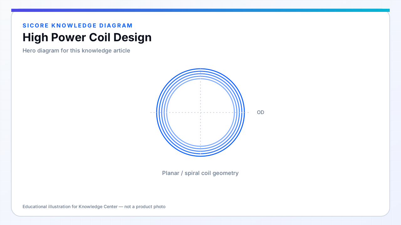
High-power coil design pushes current density, flux density, and thermal limits simultaneously. At 10–50 kW class docks, transmitter coils carry hundreds of amperes of resonant current; receivers must handle induced voltages and currents without exceeding insulation or capacitor ratings.
Scaling from a 3 kW prototype to 30 kW is not linear — Rac, ferrite saturation, and leakage flux often force new geometry rather than proportionally larger wire.
01Key limits
- AC current density in inner turns after proximity model.
- Ferrite Bpeak at min gap and max current.
- Thermal steady state at fleet duty cycle.
- EMC and leakage at full magnetomotive force.
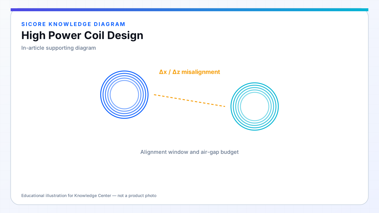
02Architecture choices
Split power across multiple coils or phases. Use thicker foil or parallel litz bundles. Active cooling on spreader plates for extreme cases. Co-design with inverter so coil MMF matches ZVS window — not maximum possible current.
03Qualification
- Extended soak at 110% rated power until thermal equilibrium.
- Impulse tests for vehicle approach mis-hit without damage.
- Insulation system aged samples before production release.