
Artículo wiki · Colección 03
Bobina Unipolar
Referencia técnica sobre Bobina Unipolar para el diseño, integración e implementación de sistemas de energía inalámbrica.
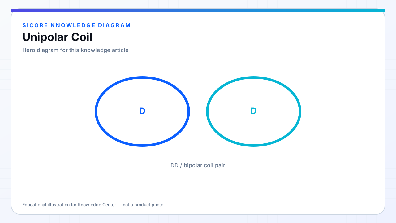
Unipolar coils produce a dominant flux component in one direction across the pad face — the typical single spiral with current returning on an inner or outer tap behaves unipolar when viewed on axis. Most industrial transmitter pads are unipolar discs or DD variants derived from unipolar segments.
Field falls off with distance and offset in patterns well documented for circular spirals, simplifying alignment specs and FOD placement relative to the coil center.
01Advantages
- Straightforward intuition for installers and field service.
- Central flux peak aids pin/cone alignment schemes.
- Simpler analytical models for first-pass L and k estimates.
02Limitations
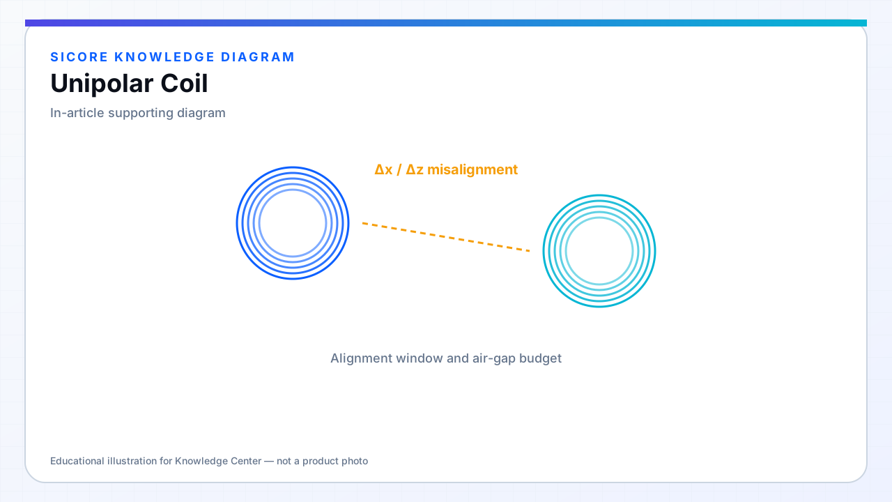
Lateral misalignment sensitivity is often worse than optimized bipolar/DD/array solutions for the same area. External metal can asymmetrically distort a unipolar field, biasing FOD if sensors assume symmetry.
03Best practices
- Keep return path compact and co-planar to preserve unipolar character.
- Use ferrite to prevent backward flux from wrapping into the wrong half-space.
- Document polarity relative to vehicle forward direction for DD-like variants.