
Artículo wiki · Colección 05
Detección de Carga
Referencia técnica sobre Detección de Carga para el diseño, integración e implementación de sistemas de energía inalámbrica.
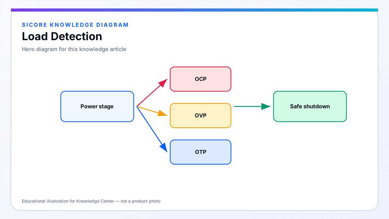
Load detection answers whether the transmitter should energize the pad at full authority. Wireless chargers must distinguish a properly coupled receiver from an empty dock, a metal cart parked nearby, or a vehicle that has not completed communication handshakes.
Industrial systems combine low-power probing, impedance signatures, and digital messaging so power ramps only after confidence is high.
01Detection signals
- Reflected impedance change when a receiver tank loads the primary.
- Secondary communication beacon or modulated backscatter on the link.
- Qi-style or custom in-band signaling confirming CC/CV readiness.
- Mechanical interlocks or pose sensors correlating robot presence with electrical signature.

02Staged power ramp
SiCore docks typically use a staged sequence: idle ping → identification → FOD baseline compare → negotiated power ramp. Each stage has tighter limits than the next. Skipping stages for faster charge sounds attractive until an empty pad fires at full bridge voltage into detuned capacitors.
03False positives and negatives
False positive load detect risks heating foreign metal; false negative detect frustrates fleet throughput. Characterize both across temperature and with neighboring steel structures. Log rejected starts — they often predict mechanical wear on guides or a failing receiver capacitor before total fault.