
Artículo wiki · Colección 04
Convertidor Boost
Referencia técnica sobre Convertidor Boost para el diseño, integración e implementación de sistemas de energía inalámbrica.
6 minArtículo 22/50Electrónica de Potencia
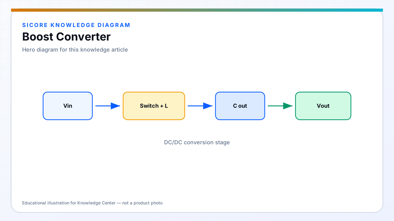
Boost converters raise voltage by storing energy in an inductor while the switch is on and releasing it to the output when the switch turns off. PFC boost stages are the dominant AC/DC front end for single-phase docks.
On vehicles, boost stages appear when battery or ultracap voltage is below the inverter requirement for motoring or when boosting rectifier output during weak coupling.
01PFC context
- Follows rectified AC with output bus typically 350–400 VDC or site-specific.
- Current mode control for shaping input current.
- Output cap sized for WPT inverter pulse load.
02Design cautions
Right-half-plane zero in continuous boost limits control bandwidth — coordinate with slow outer power loops. Startup inrush and OVP on output when load disconnects under heavy charge must be tested.
03Wireless link interaction
- Avoid beat frequencies between boost and inverter unless filtered.
- During weak coupling, boosting receiver voltage increases rectifier and SR stress — limit with link power control.