
Artículo wiki · Colección 04
IGBT en Energía Inalámbrica
Referencia técnica sobre IGBT en Energía Inalámbrica para el diseño, integración e implementación de sistemas de energía inalámbrica.
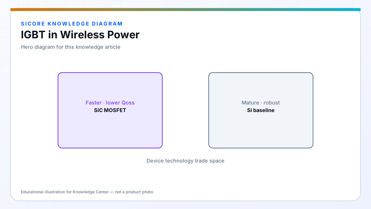
IGBTs dominate low-frequency high-power switching where MOSFET conduction loss would dominate. Most WPT coil inverters at 85–150 kHz use MOSFETs or wide bandgap devices — IGBTs appear in the dock AC/DC stage, pre-regulators, or legacy low-frequency IPT systems.
Know the boundary: above roughly 20–40 kHz, IGBT switching loss typically favors unipolar devices for new WPT inverter designs.
01Typical roles
- Three-phase PFC or rectifier stages at line frequency modulation.
- Very high power motor-drive shared infrastructure feeding DC bus to WPT.
- Older kilohertz-range IPT installations still in field service.
02Coexistence with WPT inverter
IGBT front end plus MOSFET WPT inverter is a common partition. Bus stability and harmonic content from the IGBT stage must be validated with WPT full load. Gate drive and protection for IGBT modules differ — separate service manuals for field teams.
03Migration notes
- Retrofit paths from IGBT IPT to SiC MOSFET WPT need new magnetics and EMC qualification.
- Do not assume IGBT short-circuit rating transfers to high-frequency tank fault scenarios.