
Artículo wiki · Colección 04
Filtro EMI de Entrada
Referencia técnica sobre Filtro EMI de Entrada para el diseño, integración e implementación de sistemas de energía inalámbrica.
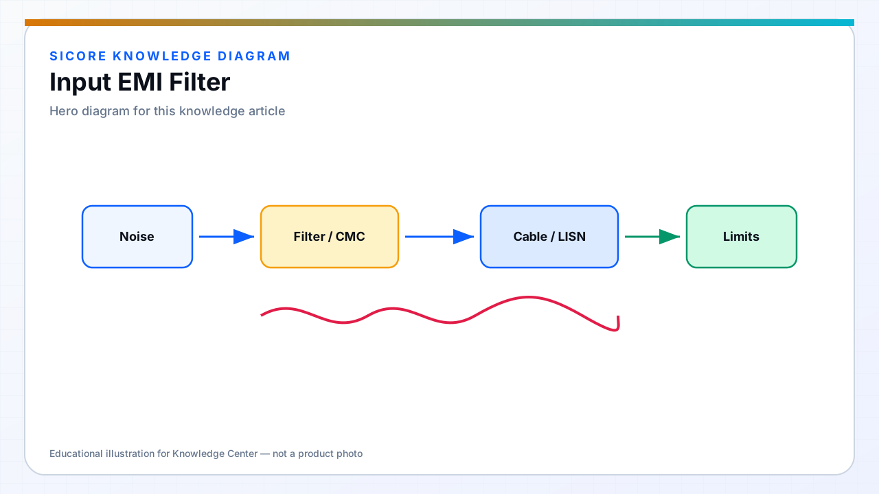
Input EMI filters sit between facility AC and the dock PFC or rectifier, attenuating conducted emissions at switching harmonics and WPT-related sidebands coupled back to the line. Filter design must consider source impedance from the grid and load impedance from PFC — mismatch can cause gain peaks.
Filters are not plug-and-play catalog parts at multi-kW — validate on the integrated dock.
01Components
- Common-mode chokes on line and neutral.
- X capacitors for differential mode; Y capacitors for common-mode — leakage limits touch current.
- Optional damping to avoid resonance with long supply cables.
02Installation
Filter input side faces the grid; output toward PFC. Keep filter to PFC wiring short and separated from WPT coil cables inside the pedestal. Ground bond per EMC plan — floating filter grounds cause mystery failures.
03Maintenance
- Y cap failure increases touch leakage — include in periodic safety checks.
- Document approved filter replacements — generic filters may detune compliance.