
Artículo wiki · Colección 04
Corrección del Factor de Potencia
Referencia técnica sobre Corrección del Factor de Potencia para el diseño, integración e implementación de sistemas de energía inalámbrica.
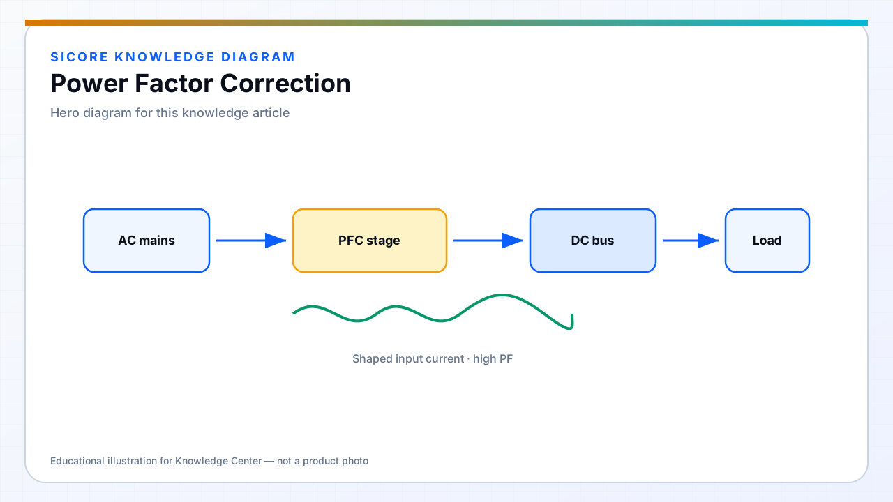
Power factor correction shapes AC input current to follow voltage, improving real power delivery and meeting harmonic regulations. Fixed docks without PFC draw peaky current that heats neutral conductors and can disturb other factory loads.
The PFC output bus feeds the WPT inverter. Bus voltage ripple and control bandwidth must support fast load steps when vehicles connect and demand power.
01Topologies
- Boost PFC for single-phase dock feeds — common and mature.
- Interleaved or bridgeless variants for efficiency at higher power.
- Three-phase Vienna or similar for high-power charging lanes.

02Interaction with WPT
PFC control loops are slower than inverter loops. Bulk capacitor energy buffers fast WPT load pulses. Size bulk cap for ripple at twice line frequency and for hold-up — undervoltage lockout on the inverter should not nuisance-trip during normal PFC regulation.
03Site planning
- Aggregate harmonic contribution when many docks share one transformer.
- Monitor PF and THD during commissioning.
- Coordinate inrush and PFC soft-start with upstream breakers.