
Artículo wiki · Colección 11
Protección contra Sobretensión
Referencia técnica sobre Protección contra Sobretensión para el diseño, integración e implementación de sistemas de energía inalámbrica.
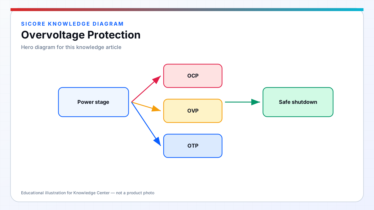
Overvoltage conditions threaten inverter capacitors, receiver SR FETs, and vehicle battery systems when energy storage elements resonate, loads disconnect suddenly, or mains disturbances propagate through the power chain. High-Q resonant WPT circuits can produce voltages exceeding steady-state design by significant margin during no-load, misalignment, or intermittent coupling — SiCore protection must act before component absolute maximum ratings are exceeded.
Dock products face AC mains overvoltage from utility events and facility power factor correction switching; receivers face battery load dump when BMS disconnects during charge and inductive kick from receiver output inductors — protection topology differs but response time requirements are similarly stringent.
01Protection mechanisms
- TVS and MOVs: clamp transients on AC input, DC bus, and gate-driver supplies with coordinated energy rating.
- Active clamping: secondary-side or primary-side circuits that dissipate or return excess resonant energy during unload.
- OVP comparators: hardware shutdown when tank voltage, bus voltage, or output voltage exceeds tiered thresholds.
- Soft shutdown ramp: controlled power reduction before mechanical disconnect to limit inductive overshoot.
- BMS handshake: receiver ceases current demand and opens contactors on OVP detection before battery overcharge.
02WPT-specific overvoltage scenarios
Open-circuit or near-open secondary during dock energization raises primary tank voltage — SiCore firmware inhibits full power until valid coupling and load confirmation. Foreign objects with high Q can sustain resonant voltage elevation — FOD and overvoltage protection operate in parallel with independent hardware paths. Multi-turn receiver coils and tuning capacitors require surge-rated components with margin for alignment tolerance extremes.
Receiver load dump when AGV departs while still coupled or when BMS opens under fault produces voltage spike on output — TVS sizing and output capacitor ESL minimization reduce peak; firmware logs event for fleet safety review. Dock AC OVP disables PFC and inverter when mains exceeds continuous rating; brief transients are absorbed by front-end protection with selective ride-through per IEC 61000-4-11 test levels.
03Design verification
Hi-pot and surge immunity tests validate clamp coordination without cascading failure. Oscilloscope verification of peak voltage at worst alignment, no-load, and sudden unload conditions gates release — simulation alone is insufficient for high-Q nonlinear behavior. Component derating applies to capacitors and FETs at maximum clamp energy; field replacement parts must match rated avalanche and surge specifications.