
Artículo wiki · Colección 03
Diseño de Entrehierro
Referencia técnica sobre Diseño de Entrehierro para el diseño, integración e implementación de sistemas de energía inalámbrica.
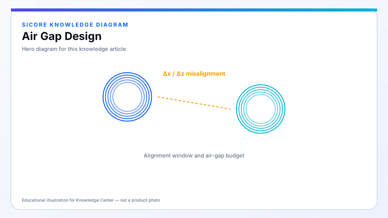
Air gap is the separation along the flux axis between transmitter and receiver coils, including encapsulation, floor tile thickness, vehicle belly clearance, and intentional standoff. Gap directly scales magnetizing requirements and coupling; it is one of the strongest levers in dock specification.
AGV docks often target a nominal gap with ± few millimeters tolerance from floor wear, tire inflation, and load compression. AMR applications with suspended receivers may specify a larger nominal gap with tighter lateral alignment.
01Gap budget components
- Pad encapsulation and top surface wear layer.
- Vehicle receiver cover and any debris gap (required in dirty environments).
- Manufacturing tolerance stack on mount heights.
- Thermal expansion at operating temperature.
02Design implications
Larger gap demands more turns, higher magnetizing current, or larger coil area to recover k. Soft-start and foreign-object detection thresholds scale with gap because field strength at the surface changes. Document minimum and maximum gap on the pad label — maintenance crews replace tiles without recalculating.
03Validation
- Test at min, nominal, and max gap with full power cycle.
- Verify FOD still detects test objects at max gap — sensitivity drops if gap grows unbounded.
- Check mechanical: max gap must not allow coil impact at min compression.