
Artículo wiki · Colección 03
Optimización de Acoplamiento
Referencia técnica sobre Optimización de Acoplamiento para el diseño, integración e implementación de sistemas de energía inalámbrica.
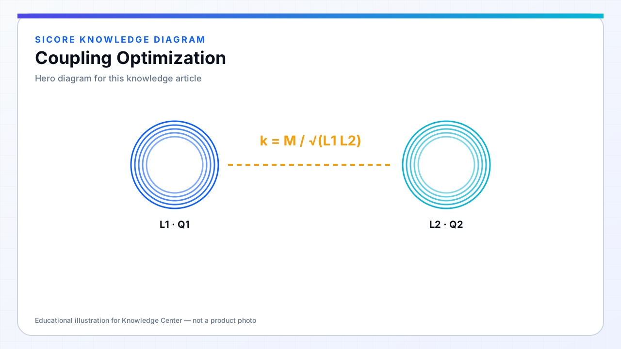
Coupling optimization targets the highest practical k across the alignment envelope without exceeding loss, EMC, or mechanical limits. It is a multi-objective problem: peak k at center alignment is less important than minimum k at worst-case offset for fleet uptime.
Tools include coil sizing, ferrite flux concentration, reducing anti-aligned flux components, and matching transmitter/receiver area ratios. Over-optimization on a steel-less bench misleads — optimize on representative chassis fixtures.
01Levers
- Increase overlapping area (within vehicle packaging).
- Reduce gap via mechanical design — often cheaper than more copper.
- Ferrite back-plates to reduce reluctance of the flux path.
- Receiver coil closer to the outer edge of the vehicle footprint (watch FOD and impact).
02Diminishing returns
Chasing k above what the power stage needs increases leakage flux and neighbor interference. Very tight coupling lowers impedance and can stress compensation components. Define a k target band from system simulation, then stop when margin is met.
03Metrics
- k_min at worst misalignment for full-power operation.
- k_max for over-voltage/current checks on series capacitors.
- Coupling variation Δk for control stability analysis.