
Artículo wiki · Colección 03
Aislamiento de Bobinas
Referencia técnica sobre Aislamiento de Bobinas para el diseño, integración e implementación de sistemas de energía inalámbrica.
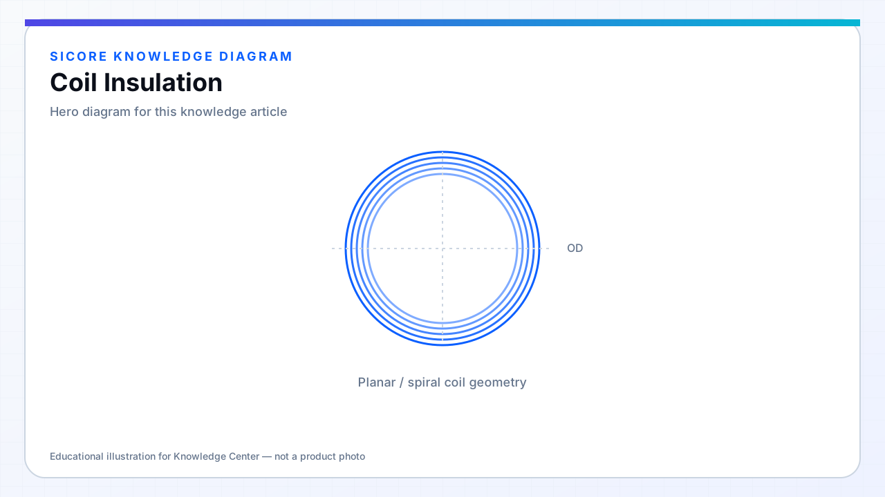
Coil insulation spans strand enamel on magnet wire, inter-turn spacing, bobbin materials, and separation from ferrite and shields. Resonant receivers can develop kilovolt-class peaks on tuning capacitors and coil terminals even at modest battery voltage — insulation must be rated for peak AC stress plus transients from switching and plug events.
Mechanical abrasion during winding, potting shrinkage, and vibration in AGV service degrade insulation over time — design and test for life, not just Hi-Pot at birth.
01Material selection
- Wire thermal class (180°C polyimide vs 155°C polyester) matched to thermal design.
- Potting compounds with dielectric strength and CTI appropriate for environment.
- Separator sheets between litz layers and ferrite where edge voltage concentrates.
02Test
Hi-Pot between coil and shield at defined AC voltage with ramp rate. Partial discharge test for high-reliability programs. After thermal aging samples, repeat Hi-Pot to catch embrittled enamel.
03Failure indicators
- Intermittent insulation breakdown shows as sudden Q drop or FOD false triggers.
- Corona staining on potting near inner turns.
- Moisture ingress in outdoor pads lowering insulation resistance.