
Artículo wiki · Colección 03
Resistencia y ESR de Bobina
Referencia técnica sobre Resistencia y ESR de Bobina para el diseño, integración e implementación de sistemas de energía inalámbrica.
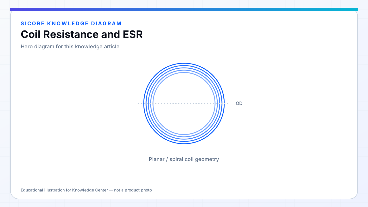
Coil resistance determines I²R loss. DC resistance from wire length and copper area is only the starting point; at tens to hundreds of kilohertz, AC resistance Rac often exceeds Rdc due to skin and proximity effects. Equivalent series resistance (ESR) in datasheets usually means the total resistive part of the coil impedance at frequency.
High Q resonant tanks circulate large currents — even milliohm increases in ESR translate to watts of heat in a pad that may already run warm from core and switching losses.
01Contributors to ESR
- Conductor material and effective area (Litz strand count, PCB oz).
- Terminations, solder joints, and bolted busbars.
- Ferrite and shield eddy losses reflected as apparent coil loss (fixture-dependent).
- Capacitor ESR in series/parallel tuning — often grouped with coil in tank Q measurements.
02Specification
State Rac at operating frequency and temperature. Include measurement fixture definition. For fleet spares, reject coils above maximum ESR even if inductance is in tolerance — efficiency and thermal performance will differ silently.
03Reduction tactics
- Litz or foil with appropriate strand sizing.
- Wider PCB traces on outer turns; parallel copper sheets.
- Move terminations out of high-field regions to reduce proximity loss.