
Artículo wiki · Colección 03
Diseño de Inductancia Mutua
Referencia técnica sobre Diseño de Inductancia Mutua para el diseño, integración e implementación de sistemas de energía inalámbrica.
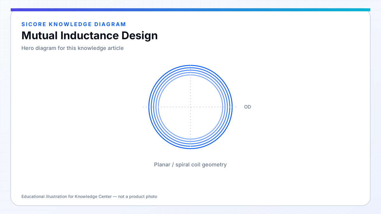
Mutual inductance M quantifies flux linkage between transmitter and receiver windings. For given self-inductances, M = k√(L1L2). M sets induced voltage on the open receiver and scales power transfer in coupled-resonator models. Designing M across the alignment envelope is equivalent to designing k with realistic L values on both sides.
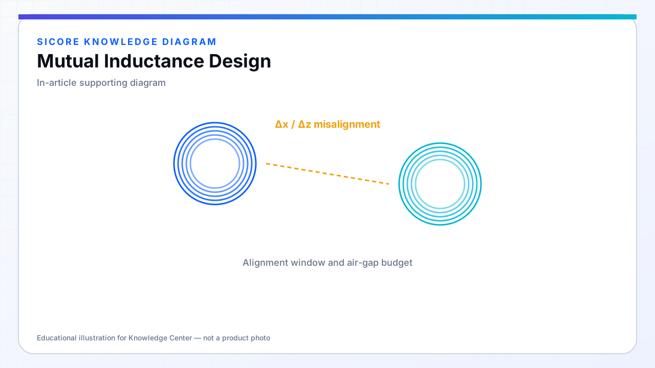
Mutual inductance is strongly positional — a single M number is always qualified by gap and offset.
01Design implications
- Higher M at same current increases received power but may narrow control margins.
- M imbalance in multi-coil arrays causes uneven segment loading.
- M coupling to foreign loops (cables, frames) creates unintended paths.
02Estimation and test
FEM extracts M from flux linkage integrals or S-parameters converted to Z-parameters. Bench test: measure open-circuit voltage on RX with known TX current, or use dual-port impedance methods. Sweep position on a grid and store M(x,y,z) for control lookup tables if used.
03System link
- Relate M to required TX current for power target at worst-case rectifier voltage.
- Check M variation does not push compensation out of soft-switching.
- Foreign metal can increase or decrease M — FOD must distinguish load from partner coil.