
Artículo wiki · Colección 03
Interacción Bobina-Chasis
Referencia técnica sobre Interacción Bobina-Chasis para el diseño, integración e implementación de sistemas de energía inalámbrica.
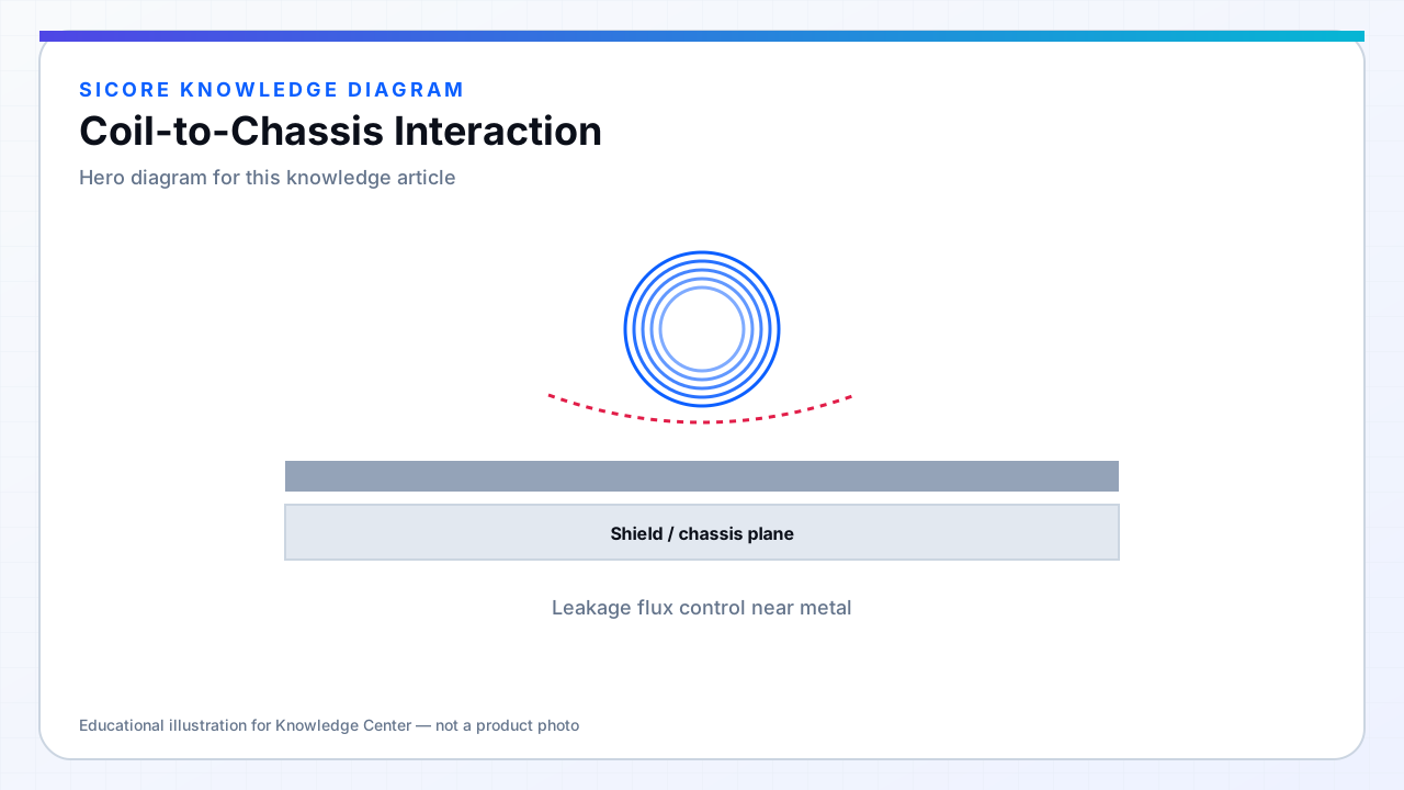
Coils never operate in free space on production docks. Steel frames, aluminum trays, fasteners, and reinforcement shift permeability and eddy-current paths. A receiver characterized on a plastic jig can measure 15–30% different L and materially different k when bolted to the AGV belly plate.
Coil-to-chassis interaction cuts both ways: chassis can shield leakage beneficially or add loss; it can also create unintended flux shortcuts that bypass the intended gap.
01Modeling and test
- Include simplified chassis CAD in FEM with conductivity assigned.
- Sweep coil mount standoff height — small changes matter.
- Measure on golden vehicle at multiple battery states (load height).
02Mitigation
Standoffs between coil ferrite and steel. Dedicated aluminum flux barriers. Relocate coil away from parallel steel rails running under the winding. Document forbidden retrofit brackets near the coil zone in service manuals.
03Signs of bad interaction
- Efficiency drops only on vehicle, not on bench mockup.
- Chassis local heating during charge.
- Navigation sensor errors correlated with charging (magnetic interference).