
Artículo wiki · Colección 03
Control de Flujo de Fuga
Referencia técnica sobre Control de Flujo de Fuga para el diseño, integración e implementación de sistemas de energía inalámbrica.
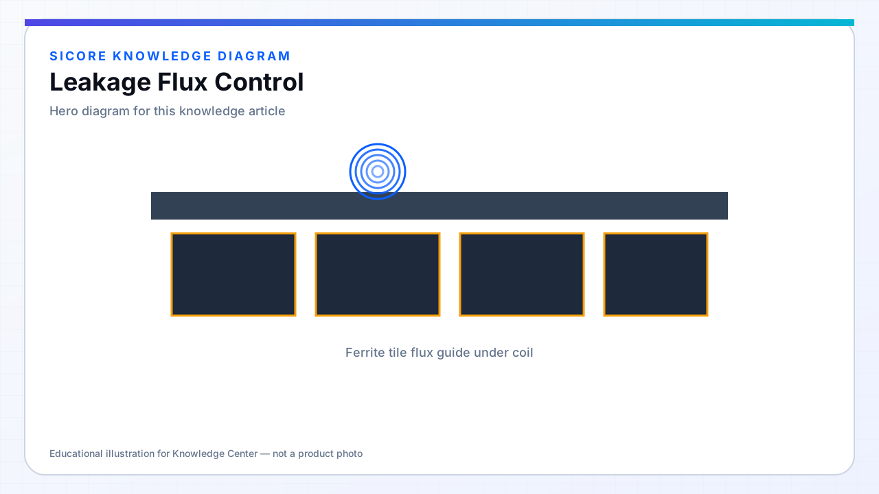
Leakage flux is the portion of transmitter flux that does not link the receiver — it wraps around shields, couples into floor steel, radiates, or induces voltages in nearby loops. High leakage increases EMC risk and heats nearby conductive structures even when main power transfer efficiency looks acceptable.
Leakage is not always bad in controlled amounts — some topologies use leakage inductance intentionally — but uncontrolled leakage near AMR sensor cables causes field failures.
01Control methods
- Ferrite back-plates and return paths sized for flux closure.
- Conductive shields with appropriate gap to limit eddy loss.
- Coil sizing matched to receiver so magnetizing flux is not excessive.
- Physical separation and orientation vs adjacent pads and cables.

02Assessment
Measure stray B-field at defined points (100 mm above pad, 500 mm lateral) during max power. Correlate with EMC scan and thermography on steel fixtures. Compare aligned vs misaligned — misalignment often increases leakage asymmetrically.
03Fleet layout
- Pad spacing standards in multi-AMR charging lanes.
- Route data cables outside leakage lobes documented in install guide.
- Avoid stacking charging bays directly above steel mezzanine beams without analysis.