
Artículo wiki · Colección 04
Pérdidas por Conducción
Referencia técnica sobre Pérdidas por Conducción para el diseño, integración e implementación de sistemas de energía inalámbrica.
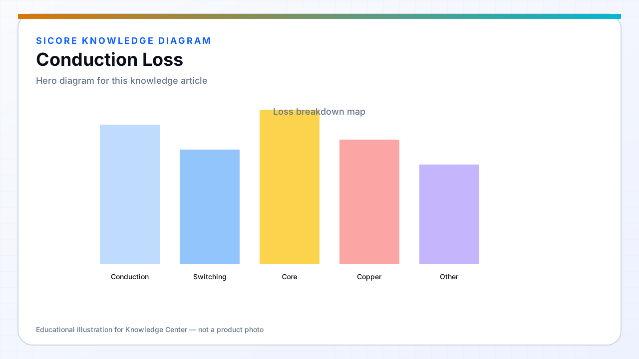
Conduction loss is the predictable dissipation when current flows through resistive elements — MOSFET RDS(on), winding AC and DC resistance, connector contact resistance, and cable copper. In high-power AGV wireless charging at moderate frequency, conduction loss often exceeds switching loss once the link is well tuned.
Every milliohm in the coil-to-battery path matters at 50 A and above.
01Major contributors
- inverter and SR MOSFET on-resistance at hot junction temperature.
- Coil Litz or copper AC resistance including proximity and skin effect.
- Bus bars, fuse holders, and charging contacts in the dock-vehicle interface.
- Rectifier or SR channel loss when diodes remain in the path.
02Reduction approaches
Parallel FETs or larger die when switching budget allows. Optimize coil conductor packing and ferrite geometry before adding power. Use four-point Kelvin sensing to find hidden resistance in assemblies. Specify maintenance for contact oxidation on mating surfaces in dirty industrial floors.
03Measurement
- Thermography under sustained charge at fleet-representative current.
- Compare calculated I²R sum to input-output efficiency gap.
- Track conduction loss drift as contacts wear over docking cycles.