
Artículo wiki · Colección 04
Diseño Térmico
Referencia técnica sobre Diseño Térmico para el diseño, integración e implementación de sistemas de energía inalámbrica.
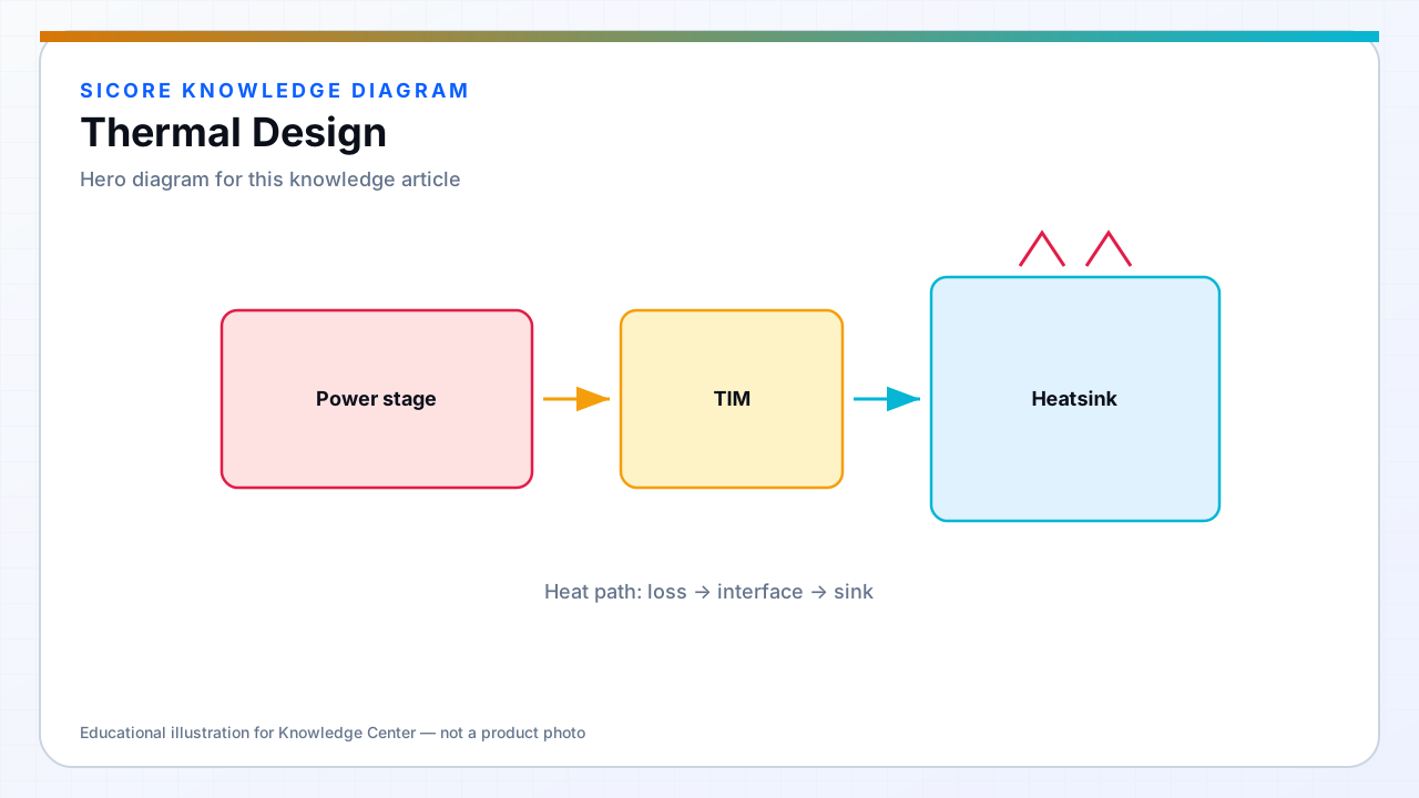
Thermal design translates loss breakdown into junction, case, and ambient temperatures that stay within device and insulation ratings. Wireless charging docks in warehouses may run near nameplate power for hours with limited airflow under floor pads or inside sealed pedestals.
Thermal failure is gradual then sudden — derating curves and fleet analytics should reflect real enclosure conditions, not open-air lab benches.
01Heat paths
- Junction to case through die attach and package.
- Case to heatsink or PCB copper through TIM and mounting pressure.
- Conduction through enclosure to ambient; forced air or liquid where passive fails.
- Coil copper and ferrite — AC loss heats windings and cores independently of the inverter.
02Design practices
Simulate or measure thermal resistance from junction to ambient on integrated assemblies. Place temperature sensors on devices, magnetics, and hot spots in the dock shell. Define control derating that reduces power before hard thermal shutdown to avoid charge interruptions mid-shift.
03Deployment
- Account for floor temperature, dust, and blocked vents in AMR aisles.
- Specify cleaning procedures that do not compress TIM or warp pad covers.
- Record thermal alarm history — recurring hot spots indicate design or alignment issues.