
Wiki article · Collection 11
Electrical Isolation
Engineering reference on Electrical Isolation for wireless power system design, integration, and deployment.
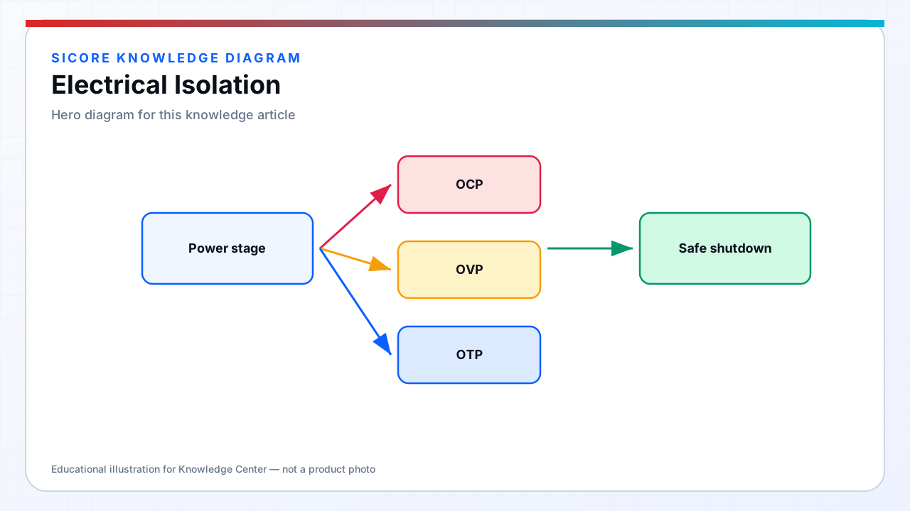
Electrical isolation prevents hazardous energy transfer between circuits at different potential — essential where SiCore dock controllers connect facility AC mains to resonant tank circuits operating at hundreds of volts and where receiver rectifiers interface with vehicle battery systems that may share or float relative to chassis ground. Isolation barriers protect maintenance personnel accessing dock pit controllers, AGV service technicians working on belly-mounted receivers, and facility electricians during concurrent charging operations.
Wireless power transfer provides inherent isolation across the air gap for power delivery, but dock and receiver products still require galvanic isolation on signal paths, auxiliary supplies, communication interfaces, and any conductive connection between vehicle and fixed installation — grounding strategy and isolation rating must be co-designed.
01Isolation barriers and ratings
- Mains to SELV/PELV: reinforced or double insulation between AC input and control electronics per IEC 60664 for rated mains voltage and overvoltage category.
- Gate driver isolation: isolated gate drivers or pulse transformers between MCU domain and high-side/low-side FET drive on inverter bridges.
- Communication isolation: digital isolators on CAN, Ethernet, and safety IO crossing the mains or battery boundary.
- Creepage and clearance: PCB layout and mechanical spacing scaled for pollution degree, altitude derating, and material CTI.
- Working voltage vs test voltage: hipot validation at 2× mains + 1000 V or per product standard for type and routine tests.
02Isolation in dock and receiver topology
SiCore dock AC front-end uses isolated PFC and inverter control — the resonant tank and coil remain on the hot side of the isolation barrier with current and voltage sensing brought across via isolated amplifiers or optical links. Floor-flush installations expose pit interiors to moisture and conductive debris — pollution degree II or III selections drive conformal coating, sealed enclosures, and increased creepage on mains-side assemblies.
AGV receivers may operate with battery negative bonded to chassis or fully floating per BMS architecture — receiver isolation ratings accommodate maximum battery voltage plus transients without breakdown to vehicle frame. Isolation monitoring (IMD) on certain dock configurations detects degradation of basic insulation to ground before shock hazard develops — required in some EV WPT standards and evaluated for industrial SiCore deployments with conductive floor plates.
03Verification and maintenance
Type testing validates isolation at extreme humidity and temperature; routine production hipot verifies no assembly defects. Service procedures define which covers may be opened under lockout/tagout and which capacitors require discharge confirmation before contact. Isolation failure modes — cracked optocouplers, moisture ingress at cable glands, pinched insulation during pit installation — are tracked in field reliability data and addressed through design and installation guide revisions.