
Wiki article · Collection 11
Thermal Protection
Engineering reference on Thermal Protection for wireless power system design, integration, and deployment.
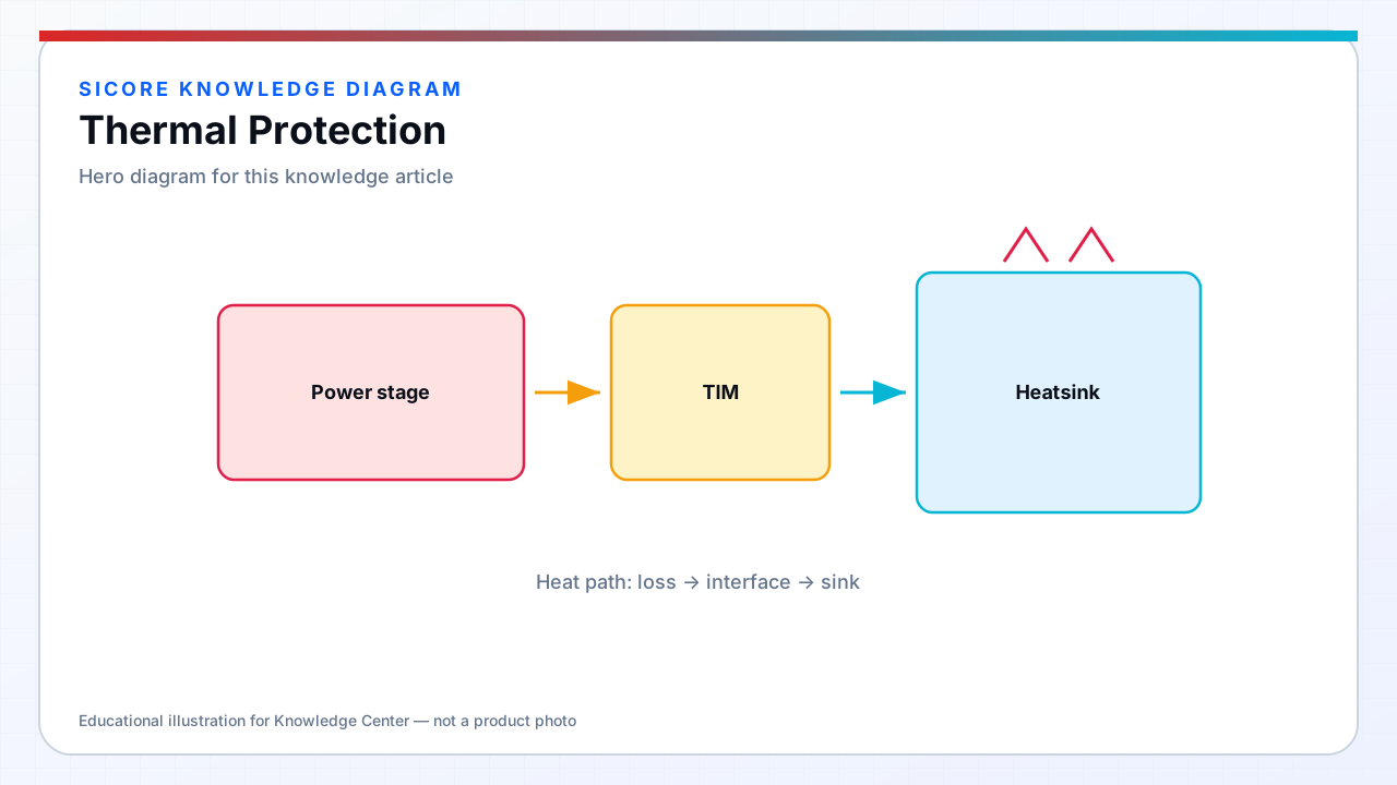
Thermal protection prevents fire, component explosion, and insulation breakdown when heat generation exceeds dissipation — acute concern for floor-flush dock pits with limited airflow, summer ambient extremes, and continuous AGV rotation charging at 90%+ duty cycle. SiCore systems monitor dozens of thermal nodes: IGBT and SR FET heatsinks, resonant capacitors, coil windings, ferrite back-plates, AC filter chokes, and enclosure interior air.
Thermal limits interact with power control — graceful derating preserves partial fleet availability during HVAC failure or pit debris blocking ventilation grilles; hard shutdown protects hardware when soft limits are exceeded or sensor fault is detected.
01Sensing and control
- NTC and RTD arrays: multi-point measurement with median and plausibility voting against stuck sensors.
- Silicon junction temperature estimation: I²t modeling from current waveforms where direct die sensing unavailable.
- Thermal derating: reduce charge power proportionally between warning and critical thresholds.
- Fan and pump control: variable speed with fault feedback — stalled fan triggers immediate power reduction.
- Receiver thermal: belly enclosure hotspot monitoring with CAN telemetry to fleet thermal dashboard.
02Mechanical thermal design
Dock pit thermal design balances IP rating with conduction paths to surrounding concrete and optional forced air from facility plenum. Potting and thermally conductive gap filler improve capacitor and inductor heat spreading but complicate service — modular replaceable subassemblies preferred where mean time to repair targets demand. Receiver designs account for road grime insulating belly pan and reduced underbody airflow when vehicle stationary during charge.
Thermal runaway on battery is outside direct dock control but influenced by charge power persistence — SiCore coordinates derating with BMS temperature requests and aborts charge when receiver or dock reports critical threshold regardless of BMS charge demand.
03Validation and fleet monitoring
Thermal validation includes blocked vent testing, 50 °C ambient soak at rated power, and fault injection on sensor open/short. Fleet analytics plot thermal trend per pad — gradual rise indicates filter clogging, coil insulation degradation, or refrigerant loss in climate-controlled pits. Thermal protection events are safety-logged with pre-trip temperature trace for root cause analysis; repeated trips trigger maintenance work order before catastrophic failure.