
Wiki article · Collection 11
Emergency Shutdown
Engineering reference on Emergency Shutdown for wireless power system design, integration, and deployment.
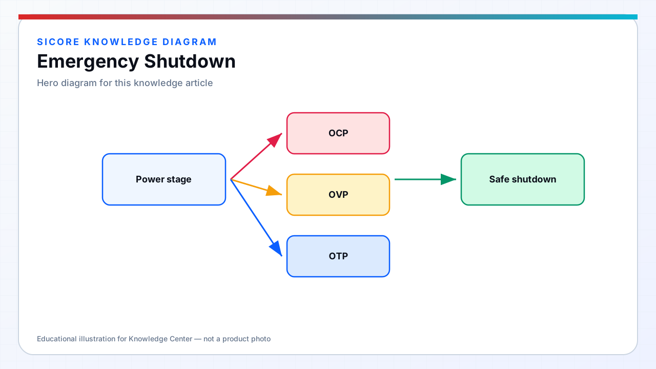
Emergency shutdown provides operator and automated safety system ability to rapidly transition charging and associated hazards to a safe state — removing power from resonant tank, disabling vehicle motion enable, and signaling fleet management that the zone is unsafe. SiCore docks interface with facility mushroom E-stops, AGV-mounted safety PLCs, light curtain outputs, and fire alarm interlocks common in warehouse installations.
Response must be deterministic: hardware paths disable gate drivers independently of software load; software confirms shutdown and holds safe state until qualified reset — preventing automatic restart into occupied fault zones after E-stop release.
01Shutdown paths and timing
- Category 0/1 stop alignment: remove motive power to inverter within defined ms via redundant disable circuits.
- E-stop chain: series-connected NC contacts cutting safety relay coil — broken wire fails safe.
- Safe state definition: zero intentional WPT field, discharged tank within bleed time, interlock latched.
- AGV STO output: dock asserts charge-prohibit and STO-coordinated signals to vehicle safety controller.
- Visual indication: pad status LED and optional horn confirm shutdown state to approaching operators.
02System coordination
Multi-pad aisles define whether E-stop affects single pad, bay, or entire charger line — SiCore supports grouped zones with configurable logic documented in site safety file. Fire alarm integration typically inhibits new charge starts and ramps down active sessions rather than instantaneous dump — balancing fire spread prevention from energized equipment against battery stress from abrupt load removal, per customer fire marshal agreement.
Receiver behavior on dock E-stop: cease rectifier switching, open output contactor if fitted, and report fault code on surviving communication link. Vehicle may retain battery energy but cannot accept charge until reset sequence completes — including visual inspection of pad and confirmation from fleet supervisor console.
03Reset and recovery
Reset requires deliberate action: twist-release E-stop, key switch, or authenticated fleet command — not mere fault clearance. SiCore reset sequence verifies FOD clear, LOD zone clear, thermal limits normal, and no active hardware fault before arming inverter. Post-incident review captures E-stop source, shutdown latency from scope measurement during commissioning baseline, and any override used — supporting continuous improvement of site safety procedures and SiCore interface documentation.