
Wiki article · Collection 05
Dynamic Frequency Tracking
Engineering reference on Dynamic Frequency Tracking for wireless power system design, integration, and deployment.
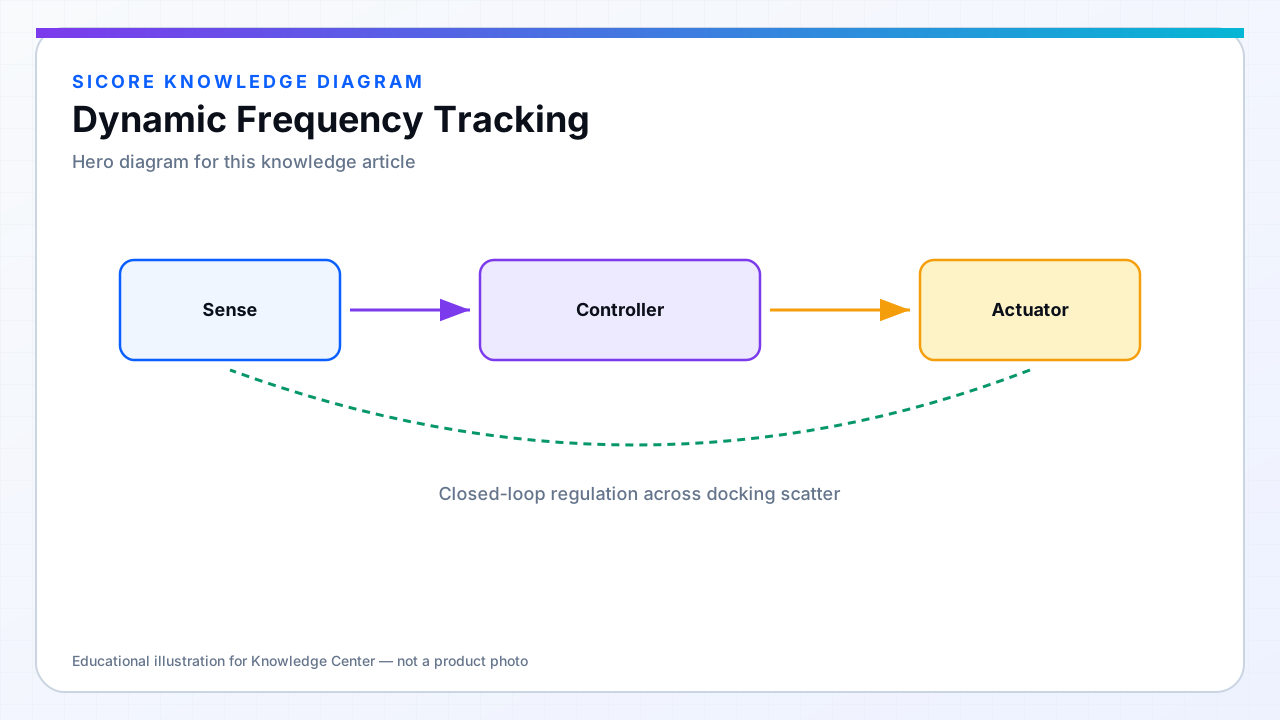
Dynamic frequency tracking (DFT) continuously estimates the resonant or gain-optimal frequency of the coupled tanks and steers the inverter to follow it. In wireless docks, that target moves: gap changes mutual inductance, ferrite temperature shifts permeability, and battery load moves the reflected impedance.
A fixed-frequency charger tuned at 25 °C bench conditions will detune on a hot summer aisle or after the fifth back-to-back charge when pad ferrite has stored heat.
01Tracking methods
- Phase-dip or impedance-peaking search around the last known good frequency.
- Perturb-and-observe on delivered power or tank current magnitude with bounded step size.
- Model-based prediction from alignment telemetry to shrink search time at dock start.
- Lock-out bands near bifurcation regions where frequency splitting creates dual peaks.

02Interaction with ZVS
The tracked frequency must stay on the correct side of resonance for the chosen modulation scheme — tracking peak power alone can wander into hard-switching corners. SiCore controllers co-optimize frequency and phase with a ZVS feasibility check each update.
03Fleet-visible benefits
Shorter settle time after the robot parks means more charging seconds per dock window. Consistent tracking reduces failed starts caused by the inverter hunting across a split gain curve when alignment is good but temperature is elevated.