
Wiki article · Collection 05
Dynamic Impedance Matching
Engineering reference on Dynamic Impedance Matching for wireless power system design, integration, and deployment.
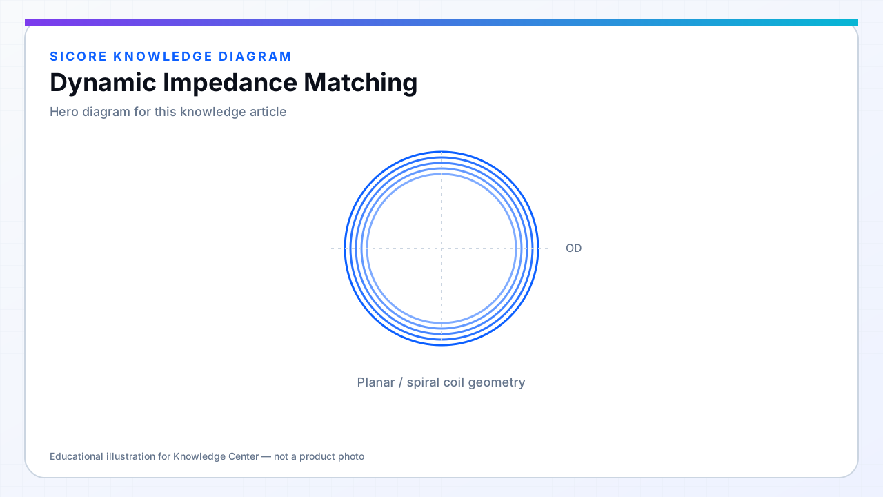
Static compensation networks are designed for a nominal k and load. Dynamic impedance matching adds actuators or switched elements so the primary and/or secondary can retune when reflected impedance moves outside the efficient band.
This is especially valuable on AMR fleets where no two parking poses are identical and receiver boards may differ by retrofit generation.
01Actuator options
- Switched capacitor banks on primary or secondary tanks with precomputed safe combinations.
- Variable inductance via switched tap windings or saturable elements (used cautiously for loss).
- Fine adjustment through phase shift and frequency when mechanical tuning range is insufficient.
- Receiver-side active rectifier or post-regulator impedance shaping for CC/CV transitions.
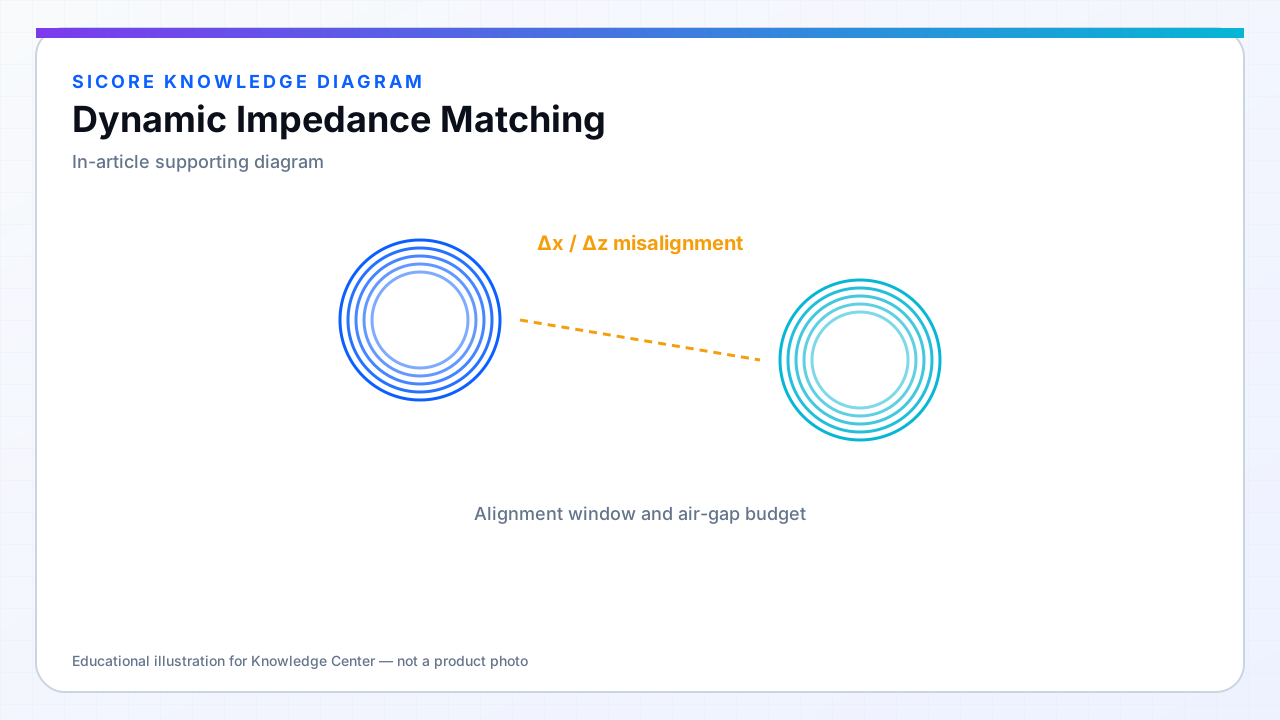
02Control strategy
Matching loops run slower than current loops but faster than thermal drift. SiCore maps safe actuator states offline across k and R_load so runtime selection is table-driven with continuous refinement from live measurements — avoiding ad hoc capacitor switching that rings the tank into over-voltage.
03When static compensation is enough
Tight mechanical guidance and narrow k windows may not justify switched networks. Dynamic matching pays off when dock repeatability is measured in centimeters, not millimeters, or when one pad serves multiple vehicle footprints.