
Wiki article · Collection 09
Heat Sink
Engineering reference on Heat Sink for wireless power system design, integration, and deployment.
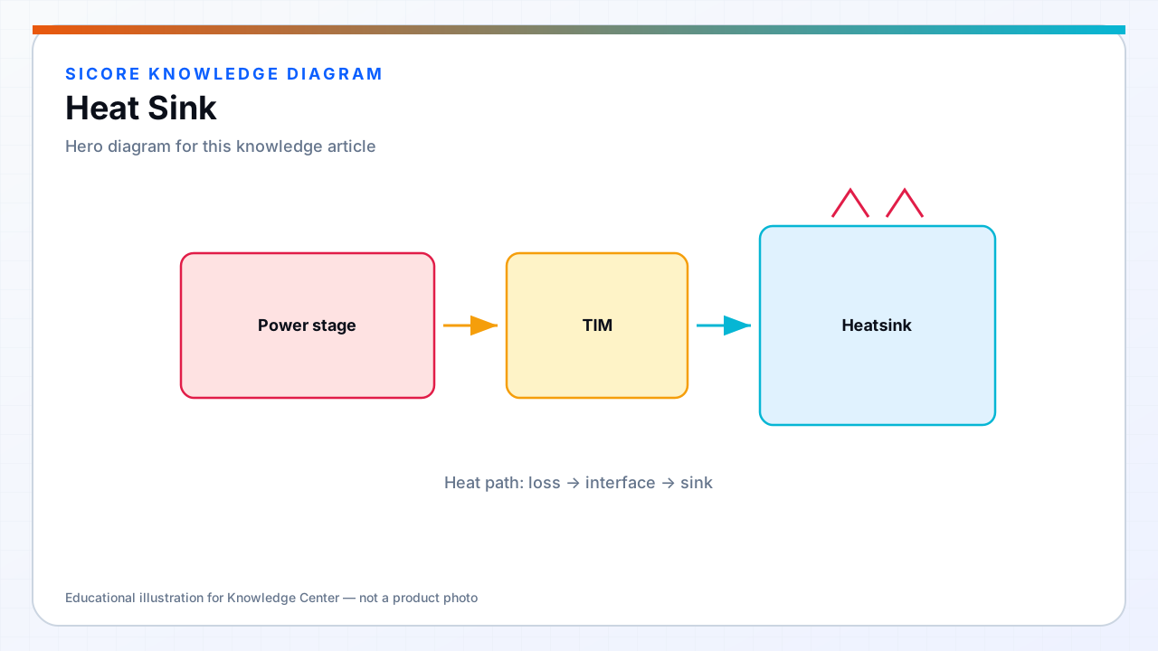
Heat sinks extend effective surface area for FET arrays, PFC stages, and DC bus capacitors that cannot rely on PCB copper alone at multi-kilowatt wireless power levels. SiCore dock designs balance heat sink fin height against floor pit depth and pedestrian/equipment clearance; receiver designs trade fin volume against under-vehicle ground clearance and debris ingress.
Heat sink performance is defined by thermal resistance chain from junction to ambient — not catalog °C/W in isolation. Interface materials, mounting pressure, and airflow direction dominate as often as fin geometry.
01Heat sink types in WPT products
- Extruded aluminum profiles with optimized fin pitch for natural convection in sealed dock boxes.
- Bonded fin or skived modules for receiver inverters where height budget is tight but width is available.
- Vapor chamber or heat pipe spreaders when FETs scatter across PCB and must equilibrate before fins.
- Dock plate as structural heatsink: machined aluminum pad surface doubles as coil back-plate thermal mass.
- Remote fin stacks ducted to pit sidewall vents when electronics sit in low-airflow center cavity.

02Thermal resistance budgeting
SiCore budgets RθJA in stages: RθJC from datasheet at Tj max operating point, RθTIM from interface material and flatness spec, RθBA from sink vendor curve at measured airflow or natural convection orientation. Margin of 10–15 °C below Tj max at 45 °C ambient and rated power is standard; 50 °C ambient sites require explicit derating or upgraded sink.
Parallel FETs assume current sharing within 10% — unequal Rds(on) or layout imbalance creates localized hotspot that average junction math misses. Thermally coupled FETs on shared spreader reduce spread; independent small sinks per device require per-device validation.
03Mechanical and maintenance integration
Dock heat sinks mount with captive screws and defined torque to preserve TIM compression without PCB flex cracking gate driver traces. Removable lid designs expose sink fins for compressed-air maintenance in dusty warehouses. Receiver sinks avoid sharp fin edges facing upward into debris paths; shrouded ducting or horizontal fin orientation extends service interval before airflow blockage triggers overtemperature faults.