
Wiki article · Collection 09
Heat Transfer
Engineering reference on Heat Transfer for wireless power system design, integration, and deployment.
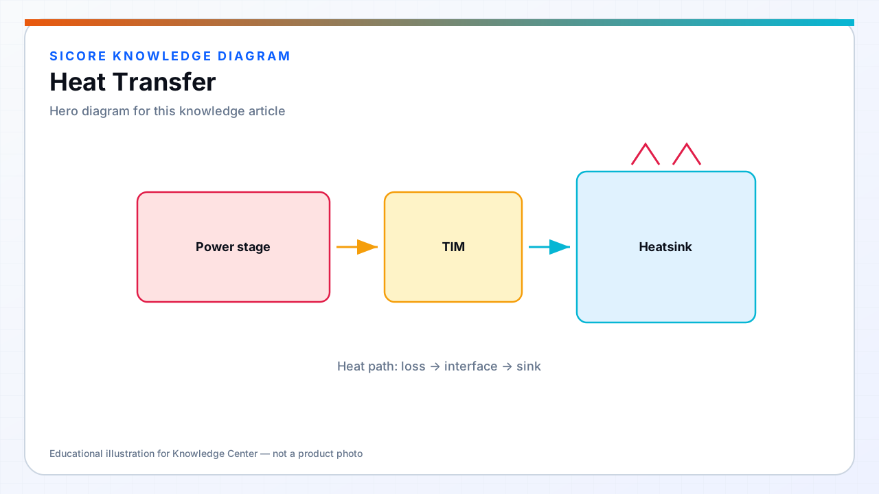
Wireless power transfer at 3–15 kW concentrates loss in compact volumes: inverter FETs, resonant tank components, ferrite cores, and receiver rectifier stages all generate heat that must reach ambient air or a facility cooling path without exceeding material limits. Heat transfer analysis is not optional margin — coil copper and ferrite temperatures directly affect coupling, detuning, and foreign-object sensitivity during extended AGV charge sessions.
SiCore thermal design treats dock transmitters and onboard receivers as coupled systems: dock floor conduction into concrete, receiver heat rejection into enclosed AMR chassis with limited airflow, and shared operational profiles where vehicles charge at peak power while logistics software schedules minimal dwell time.
01Conduction paths
- FET junction → package tab → copper pour or direct-bond heatsink → enclosure inner surface.
- Ferrite core → coil bobbin → aluminum pad plate or steel dock frame with defined contact pressure.
- High-current shunts and bus bars → dedicated thermal vias and copper spreaders on inner PCB layers.
- Receiver DC output path: synchronous rectifier FETs → chassis ground plane used as heat spreader where galvanic isolation permits.
02Convection and ambient conditions
Warehouse AGV docks operate in 0–40 °C ambient with dust, occasional wash-down near food logistics, and minimal forced airflow when pads mount flush with floor tiles. Natural convection coefficients on underside-mounted dock electronics are often 5–15 W/m²·K — optimistic spreadsheet values fail field validation. Receiver compartments inside AMR belly pans may see stagnant air pockets; SiCore receiver designs specify minimum vent area or fan duty when continuous power exceeds chassis passive capacity.
Seasonal variation matters: summer floor temperature in unconditioned aisles raises effective ambient for dock inverters mounted in shallow pits; winter cold-start improves device margins but increases NTC reading lag until steady state.
03Radiation and coupled heating
Radiation is secondary at typical dock temperatures but contributes when hot ferrite faces nearby plastic alignment guides or vehicle underbody composites without line-of-sight shielding. WPT-specific coupled heating — eddy currents in nearby steel floor plates or AMR steel frames — adds parasitic loss not captured in inverter efficiency alone. SiCore commissioning includes infrared survey of pad and vehicle underside after 30-minute rated-power session to identify unexpected heat paths before fleet rollout.