
Wiki article · Collection 03
Circular Coil
Engineering reference on Circular Coil for wireless power system design, integration, and deployment.
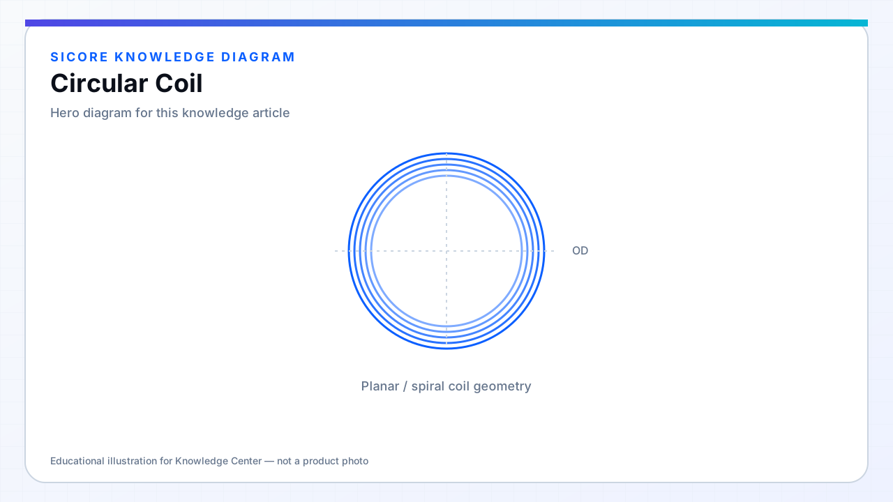
Circular coils — single spirals or concentric windings on a round former — produce nominally axisymmetric flux when centered. They are straightforward to manufacture, easy to seat in round housings, and work well when docking constrains rotation or uses a central pin/cone for repeatable alignment.
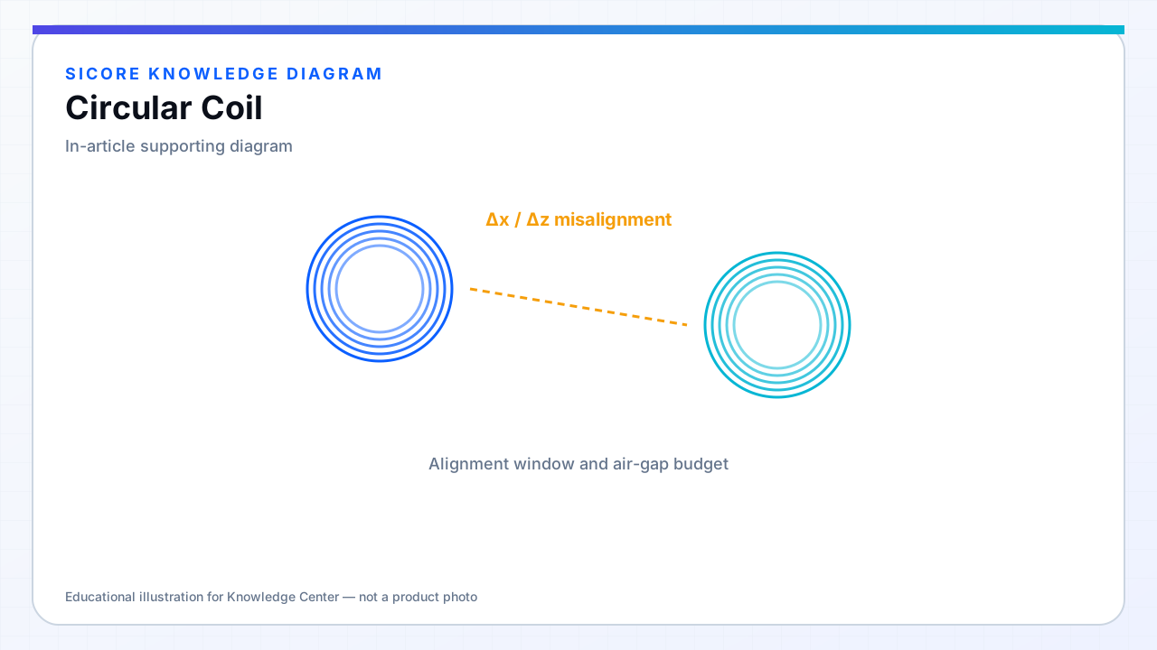
Coupling falls off with lateral offset in a roughly rotationally symmetric pattern. That symmetry simplifies specification: one misalignment curve often suffices instead of separate X and Y behavior.
01Where circular coils fit
- Pin-guided or conical self-centering AGV docks.
- Compact receiver discs on the vehicle belly.
- Applications where yaw is fixed or limited to small angles.
02Design parameters
Outer diameter sets flux capture area and typically dominates inductance for a given turn count. Inner diameter (or center clearance) affects field peaking and whether a central magnet or alignment feature can pass through. For high power, verify that inner turns do not exceed current density limits after proximity and skin effects.
03Limits
- Poor lateral tolerance compared to DD or multi-coil arrays when yaw and offset combine.
- Round footprint may waste floor space on rectangular vehicles.
- Edge fringing without ferrite can couple into nearby steel rails.