
Wiki article · Collection 03
Multi-Coil Array
Engineering reference on Multi-Coil Array for wireless power system design, integration, and deployment.
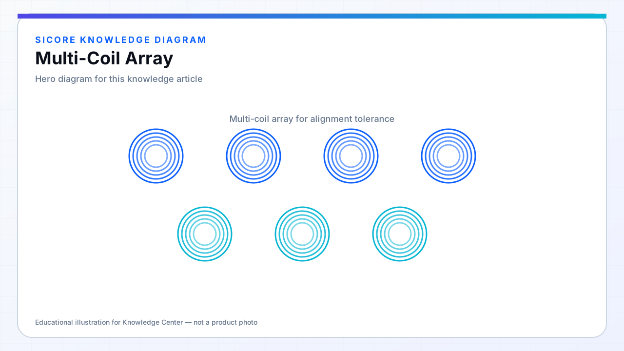
A multi-coil array places several windings on one pad and energizes one or more based on receiver position. For AMR fleets with variable stop points, arrays extend the region where k stays above a minimum without building one enormous coil with poor empty-pad loss.
Arrays add electronics: selection switches, sometimes independent inverters per segment, and detection to choose the active coil. The magnetics problem becomes coupled with sensing and thermal management per segment.
01Operating strategies
- Single active coil: simplest control, good when position sensing is reliable.
- Overlapping excitation: smoother k map, higher control complexity.
- Master/slave segments: one primary tank with auxiliary coils tuned for local boost.
02Design considerations
Mutual inductance between array elements matters — an idle neighbor coil can load the active one through coupling unless it is open-circuited or detuned. Layout must minimize cross-talk while maintaining coverage. Document maintenance: a failed segment in an array can skew field maps in non-obvious ways.
03Fleet perspective
- Commissioning includes per-segment identification and position calibration.
- Spares strategy must cover segment modules, not only the full pad.
- EMI testing with different active segments — worst case is not always the center coil.