
Wiki article · Collection 03
Spiral Coil
Engineering reference on Spiral Coil for wireless power system design, integration, and deployment.
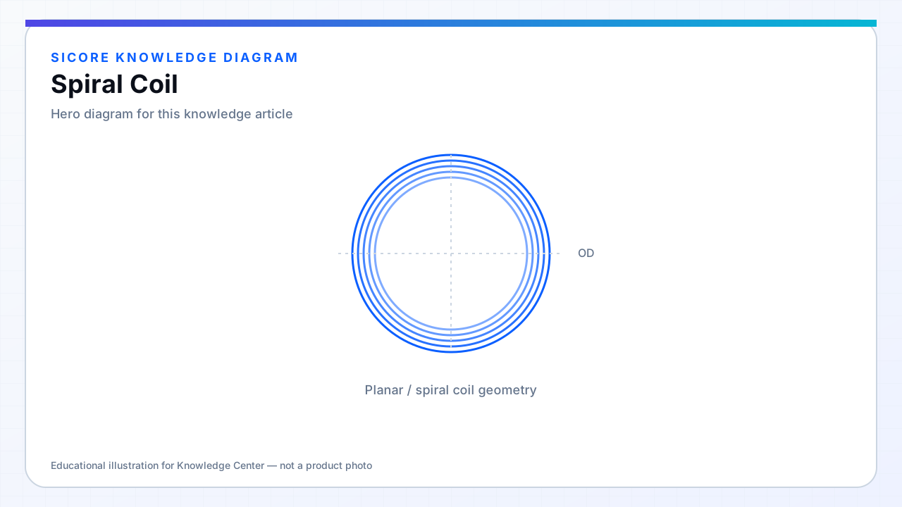
A spiral coil winds conductor outward from a center tap or continuous trace in the plane of the pad. In wireless power, spirals are the default geometry for floor-mounted transmitters and thin receiver packs because they pack inductance into a flat disc and produce a well-defined flux pattern normal to the surface.
Inductance scales roughly with turns squared times effective area, but spirals also increase inter-turn capacitance and proximity coupling between inner and outer turns. At tens to hundreds of kilohertz, those effects shift self-resonance and AC resistance — the spiral is not just a line on a drawing.
01Advantages for docks
- Flat profile for floor pads and under-vehicle receivers.
- Predictable central flux peak useful for circular alignment guides.
- Compatible with PCB, litz, or round-wire winding on a bobbin.
- Easy to combine with ferrite tiles behind the winding.
02Design notes
Inner turns carry higher current density and see stronger proximity effect — do not assume uniform loss per turn. For large spirals, consider where to place the tap and return path so the current path does not create a net field cancelation. Simulation or measurement of the full spiral with return conductor is mandatory before freezing artwork.
03When to choose something else
- Very elongated pads may favor rectangular or DD shapes for better lateral k.
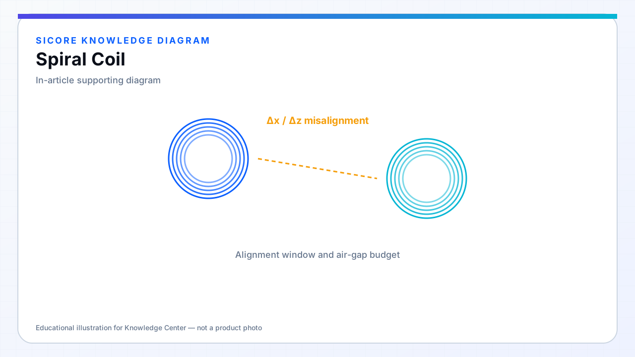
- Multi-coil arrays when a single spiral cannot cover the alignment window.
- 3D solenoid segments when vertical gap dominates and planar area is limited.