
Wiki article · Collection 03
Rectangular Coil
Engineering reference on Rectangular Coil for wireless power system design, integration, and deployment.

Rectangular coils fill oblong pad openings common on narrow AGV paths and slot-shaped receiver bays. A racetrack (rounded rectangle) reduces sharp corner field crowding compared to a sharp-edged rectangle while still matching the vehicle geometry.
Inductance and field uniformity depend on aspect ratio. Long thin rectangles concentrate flux along the long edges; corners contribute less usefully to central coupling unless ferrite guides the path.
01Applications
- Floor strips or narrow charging bays in warehouse aisles.
- Receiver packs aligned with the vehicle frame rails.
- Multi-pad lanes where several rectangular segments tile a lane.
02Design guidance
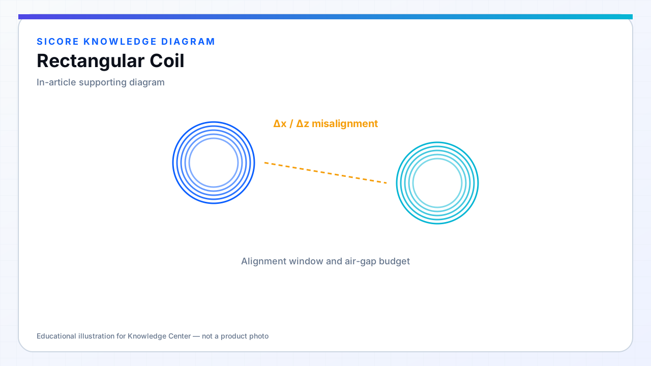
Use rounded corners or filleted traces on PCB coils to reduce high current density spots. Place ferrite tiles to close the flux path behind the straight sections first — corners are where leakage and mechanical stress concentrate. Measure k for offset along both long and short axes; rectangular coils are inherently anisotropic.
03Watchouts
- Higher inter-turn capacitance on long outer legs can lower self-resonance.
- Mechanical winding tension varies on straight vs curved sections — consistency affects L repeatability.
- Asymmetric misalignment can excite different eddy-current patterns in nearby steel.