
Wiki article · Collection 03
Three-Dimensional Coil
Engineering reference on Three-Dimensional Coil for wireless power system design, integration, and deployment.
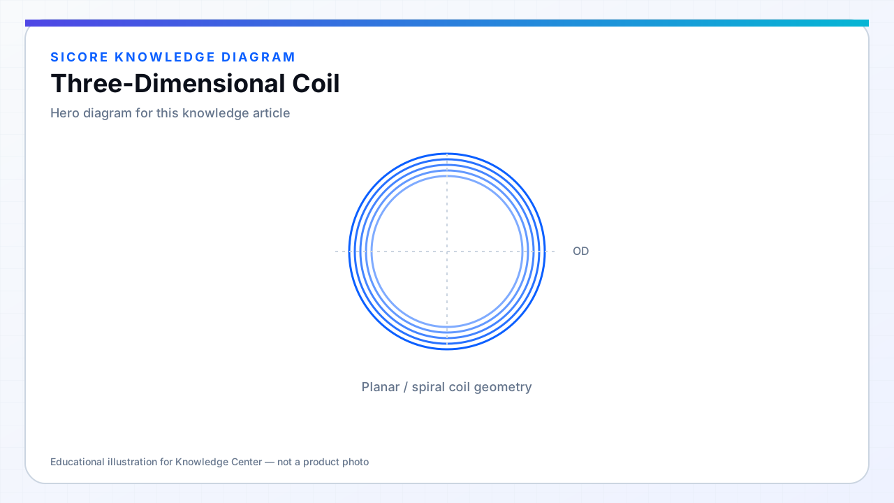
Three-dimensional coils depart from a single flat spiral by winding in height, wrapping around ferrite cores, or combining planar and vertical sections. They appear when the receiver must fit between structural members, when gap height is large relative to pad area, or when flux must be redirected around obstacles on the vehicle.
3D geometry increases manufacturing variance. Each bend adds length tolerance stack-up and changes local proximity effects. Simulation burden rises because analytical inductance formulas for flat spirals no longer apply.
01Use cases
- Low-clearance AGV bellies with recessed ferrite cores.
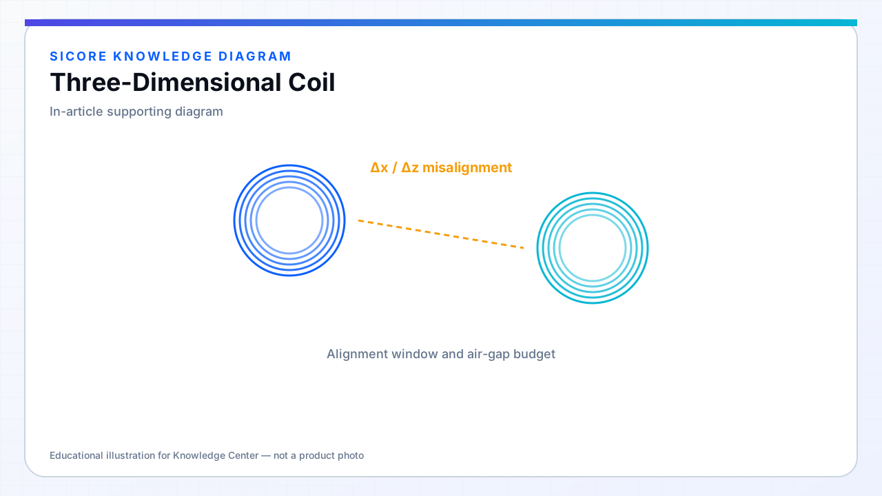
- Side-flux or angled docking where the coupling axis is not vertical.
- High-gap industrial transfers needing more turns in a constrained diameter.
02Engineering approach
Model in 3D FEM with the full current path including returns. Prototype with potting fixtures that preserve wire spacing in the vertical sections — vibration can let turns slide and shift L. Validate thermal paths: vertical sections may sit farther from the heat sink than the base plate.
03Risks
- Higher unit cost and lower repeatability than planar PCB or flat litz pads.
- Mechanical impact during docking can deform 3D formers.
- Inspection is harder — hidden turn damage under potting.