
Wiki article · Collection 03
Foreign Metal Near Coils
Engineering reference on Foreign Metal Near Coils for wireless power system design, integration, and deployment.
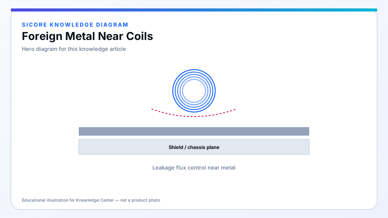
Foreign metal near coils includes intentional (chassis, rebar) and accidental (wrench left on pad, metal shavings, foil packaging) conductors and permeable objects. Time-varying fields induce eddy currents that dissipate heat, reflect flux, and detune resonant tanks. Ferromagnetic debris can saturate locally and trigger FOD or hide real faults.
Dirty warehouse environments require pads and receivers designed assuming occasional metal presence — not only clean-room commissioning.
01Effects
- Reduced or shifted k and L — power derate or control hunt.
- Hot metal — fire risk with thin shavings on energized pads.
- False FOD or missed FOD depending on algorithm and object size.
- Audible vibration on loose ferrous parts.
02Design responses
FOD tuning for site-typical debris. Pad surface slopes and covers to shed metal. Receiver skid plates that keep coil face clear. Maintenance SOP: visual sweep before energizing after floor work.
03Testing
- Standardized metal plates and shavings at defined locations in qualification.
- Repeat after encapsulation wear exposes coil area differently.
- Log FOD trips in fleet telemetry for pattern analysis (nail vs rebar shift).