
Wiki article · Collection 03
PCB Coil
Engineering reference on PCB Coil for wireless power system design, integration, and deployment.
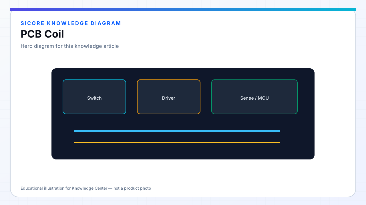
PCB coils etch the winding as copper traces on FR4 or similar laminate, enabling low-cost repeatability and easy integration with on-board tuning capacitors or sensing circuits. They suit low-to-medium power receivers, sense coils, and some transmitter segments where litz winding cost is hard to justify.
PCB coils face AC resistance limits from thin copper and via transitions in multi-layer stacks. At 100+ kHz and multi-kW, many designs migrate to litz or thick foil — but PCB remains valuable for prototypes and auxiliary windings.
01Layout practices
- Use heavy copper (2–4 oz+) or external thick-copper processing where available.
- Minimize vias in the high-current path; stitch with many parallel vias if required.
- Taper trace width from inner to outer turns to balance current density.
- Keep gap between turns consistent — etch undercut affects capacitance.
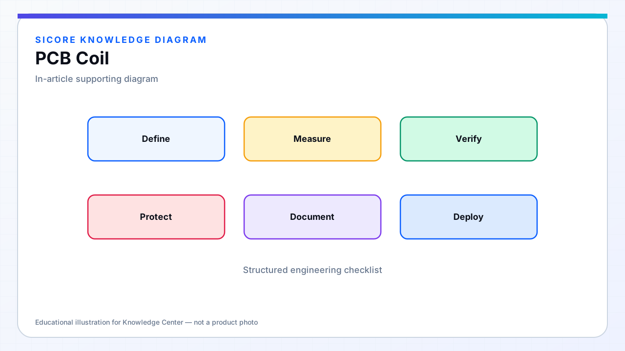
02Electrical validation
Measure L and self-resonant frequency on bare board and after potting — dielectric loading shifts capacitance. Include solder mask and epoxy in FEM dielectric regions when simulating. Plan test points for fixture probes without cutting traces.
03Production
- Panelize with impedance test coupons per lot.
- Control laminate Dk variation between PCB vendors.
- Document max reflow cycles — rework can delaminate heavy copper.