
Wiki article · Collection 03
Skin Effect in Coils
Engineering reference on Skin Effect in Coils for wireless power system design, integration, and deployment.
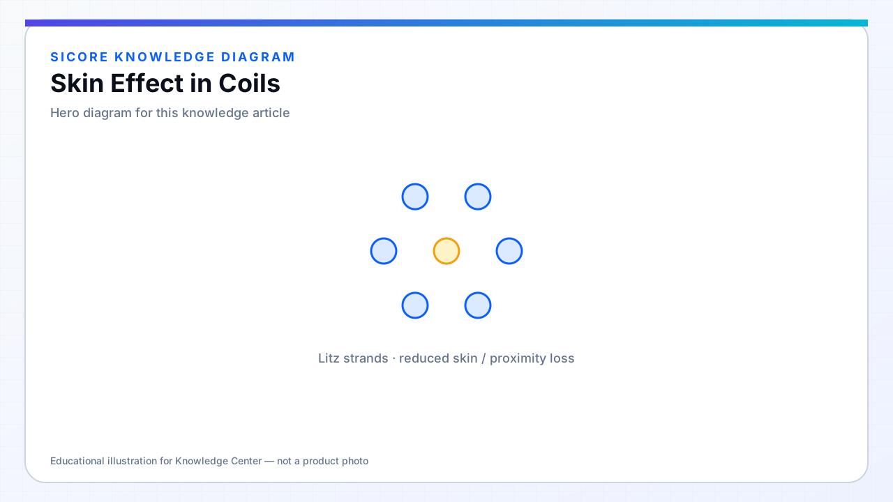
Skin effect forces AC current toward the conductor surface as frequency rises, effective cross-section shrinks and AC resistance rises above DC value. Skin depth δ ≈ √(ρ/(πfμ)) sets the scale — at 100 kHz in copper, δ is on the order of 0.2 mm, so solid wire thicker than that wastes interior copper for current.
Coil designers feel skin effect in every multi-kW spiral unless Litz or thin foil is used. Ignoring it predicts optimistic efficiency and cold coils on paper that overheat in the warehouse lane.
01Mitigation
- Litz wire with strand diameter below δ (with bundle optimization).
- Thin copper foil or PCB traces near skin depth scale.
- Parallel conductors with appropriate spacing (careful with proximity).

02Frequency planning
Raising WPT frequency shrinks skin depth — magnetics shrink but conductor loss rises unless conductor technology upgrades. When changing frequency on an existing coil geometry, recompute Rac before assuming the same turn count works.
03Measurement
- Compare Rdc and Rac on production samples — ratio tracks process drift.
- Temperature rise test correlates with Rac better than Rdc.
- Impedance analyzer with four-wire fixture on coil terminals.