
Wiki article · Collection 08
ADC
Engineering reference on ADC for wireless power system design, integration, and deployment.
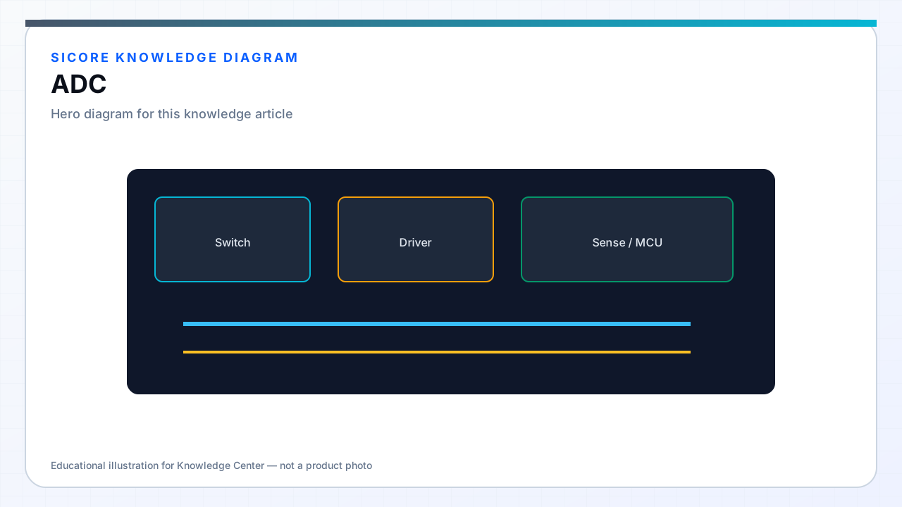
Accurate, timely current and voltage measurement underpins every protection decision and control loop in wireless charging. SiCore designs use 12–16 bit SAR ADCs with injection or regular sequences triggered from PWM center or HRTIM events so samples represent instantaneous switch-node conditions, not beat-frequency aliasing from asynchronous polling.
High-voltage sides use isolated amplifiers or sigma-delta modulators feeding MCU ADC inputs; metrology-grade shunt paths on receiver DC output support fleet energy accounting correlated with BMS coulomb counting.
01Channel planning
- Primary inverter: phase currents, DC bus voltage, resonant tank voltage or current sense.
- Receiver: rectified output voltage and current, tank current, alignment sense coil level.
- Thermal: NTC or digital temperature on FETs, coil ferrite, and receiver PCB hot spots.
- Auxiliary: grid voltage presence on dock, interlock and connector sense inputs.
02DMA, oversampling, and calibration
Circular DMA buffers deliver N-sample windows to digital filters each PWM period. Hardware oversampling improves SNR on slow thermal channels without loading CPU. Factory calibration stores offset and gain coefficients per channel in NVM; temperature drift coefficients apply for shunt amplifiers with known TC. Inline self-test injects known references during idle windows where safety analysis permits.
SiCore energy telemetry sums ADC-derived power over charge sessions and compares to pad-side AC metering during commissioning — persistent offset triggers recalibration workflows before fleet billing reliance.
03Fault and saturation handling
ADC readings outside physical range flag sensor fault rather than commanding maximum power. Saturation detection on current channels during FOD events distinguishes genuine over-current from amplifier clipping. Redundant sense paths on high-power docks cross-check primary current estimates; disagreement beyond tolerance latches derated operation or shutdown per safety case.