
Wiki article · Collection 08
Real-Time Control
Engineering reference on Real-Time Control for wireless power system design, integration, and deployment.
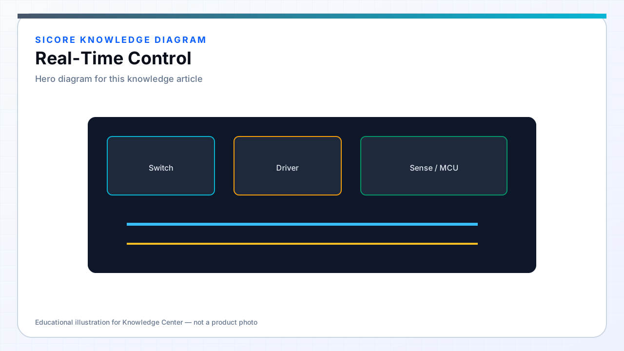
Wireless charging power stages are closed-loop systems: primary inverter switching must track resonant conditions and load changes while respecting BMS current ceilings and thermal limits. Real-time control means every sample-to-actuation path has a provable worst-case latency — not merely average loop rates on a quiet bench.
SiCore receivers regulate rectified output current and voltage presented to the onboard charger or DC bus; dock transmitters regulate primary power, phase, or frequency depending on topology ( IPT, WPT resonant, etc. ). Both sides participate in a distributed control problem linked by wireless power coupling and wired CAN negotiation.
01Loop hierarchy
- Inner loop: switching-cycle or half-cycle current regulation via duty, phase, or frequency modulation.
- Outer loop: DC output current/voltage or power setpoint tracking from BMS request.
- Supervisory: thermal derating, alignment-based power cap, session SOC target from fleet.
- Hardware loop: comparator blanking, OCP latch, and synchronous rectifier ZCD where applicable.
02Timing and jitter
ADC samples are placed in switching windows using injection triggers or HRTIM sync to minimize aliasing from ripple. Control law execution completes within one switching period at nominal frequency — typically 50–150 kHz carrier for SiCore industrial designs. RTOS jitter on outer loops is absorbed by inner-loop bandwidth separation: inner loop bandwidth 1–5 kHz equivalent, outer loop 100–500 Hz.
Comm-loss from BMS triggers ramp-down with shorter deadline than thermal derating — power must fall to zero within contractual milliseconds if CAN heartbeat stops, independent of outer-loop task scheduling.
03Commissioning and gain scheduling
Plant parameters change with coil gap and coupling k: SiCore firmware uses gain scheduling or adaptive observers rather than single PID tuned at one alignment. Commissioning tools inject step references while logging loop response; accepted gain sets are written to signed config blocks. Field drift from ferrite aging triggers re-commission prompts when phase margin estimates cross thresholds logged in diagnostics.