
Wiki article · Collection 08
Firmware Architecture
Engineering reference on Firmware Architecture for wireless power system design, integration, and deployment.
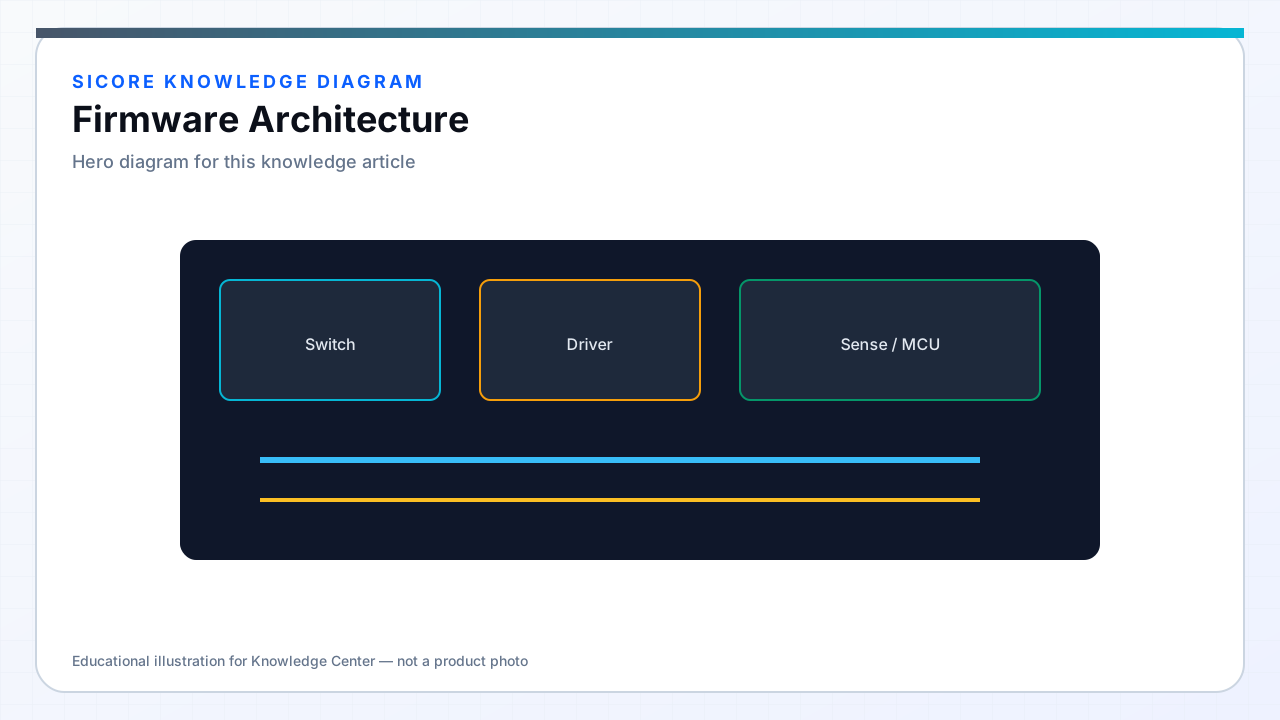
Maintainable wireless charging firmware separates concerns so power algorithms, safety monitors, and fleet interfaces evolve independently across pad generations and vehicle integrations. SiCore architecture follows a bottom-up stack: silicon HAL and board support, platform services (RTOS, flash, crypto), domain modules (power stage, alignment, session FSM), and thin adaptation layers for customer-specific CAN DBC or Ethernet schemas.
Poor layering — control loops calling socket APIs directly, or BMS parsing inside PWM ISRs — is a recurring source of field instability in industrial WPT projects; SiCore reference code enforces unidirectional dependencies.
01Layer responsibilities
- BSP/HAL: clock, pin, ADC, PWM, CAN init; no business logic.
- Platform: logging, NVM config, CRC, crypto verify, OTA staging, watchdog policy.
- Power domain: regulation loops, resonant tuning, FOD signal processing, thermal derating.
- Session domain: dock handshake, alignment qualification, charge permission, graceful ramp-down.
- Integration: DBC-driven signal maps, fleet API adapters, diagnostic DID handlers.
02State machines and configuration
Explicit finite-state machines govern session lifecycle: Idle → Alignment → Negotiation → Power Transfer → Taper → Complete, with fault and comm-loss transitions defined in tables reviewable by safety engineers. Configuration is schema-versioned JSON or binary blobs in flash — coil geometry, power limits, BMS DBC ID, and FOD thresholds — loaded at boot with CRC validation; defaults never silently override invalid customer configs.
Feature flags gate experimental algorithms behind compile-time or signed runtime config so production fleets and pilot sites diverge without forked codebases.
03Testing boundaries
Each layer exposes unit-test seams: power domain runs on HIL with simulated ADC feeds; session domain tests against CAN replay logs from field vehicles. SiCore CI builds receiver and dock images with shared platform libraries but separate application targets, ensuring OTA packages cannot flash incompatible role firmware onto wrong hardware.