
Wiki article · Collection 08
MCU Selection
Engineering reference on MCU Selection for wireless power system design, integration, and deployment.
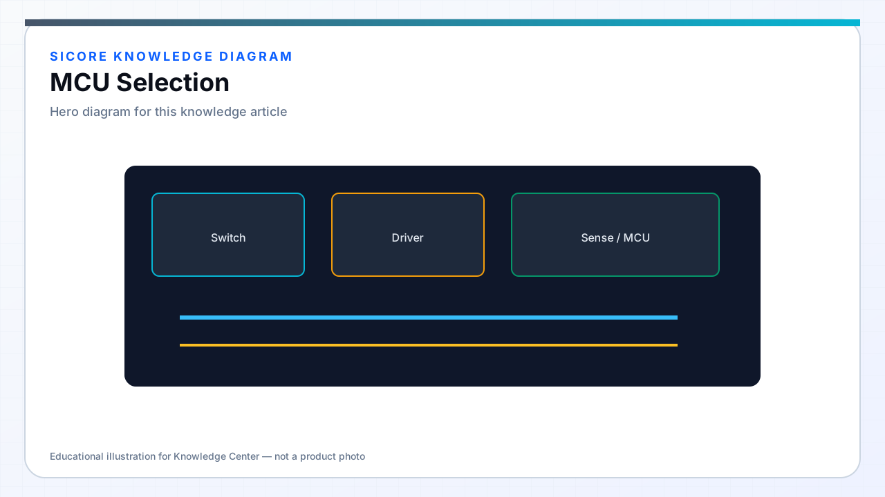
The microcontroller is the central execution engine in both dock-side pad controllers and vehicle-mounted wireless receivers. Selection is not driven by peak MIPS alone: industrial wireless charging firmware must run deterministic control loops, protocol stacks, safety monitors, and diagnostics concurrently on a part that survives warehouse temperature, EMI, and supply-chain continuity requirements.
SiCore embedded platforms typically partition high-voltage power control on dedicated gate-driver and DSP or timer-rich MCUs while a companion processor handles fleet communication, logging, and OTA — but single-chip designs remain common on compact AMR receivers where BOM and PCB area dominate.
01Selection criteria
- Peripheral mix: multiple high-resolution PWM channels, synchronized ADC triggers, CAN-FD, SPI to gate drivers, and hardware dead-time insertion.
- Deterministic timing: dedicated motor-control timers, DMA for ADC streams, and predictable interrupt latency under load.
- Memory: flash headroom for dual-bank OTA, RAM for filter buffers and protocol stacks without external SDRAM.
- Safety and quality: AEC-Q100 or industrial temperature grade, ECC flash where available, documented FMEDA path for SIL-capable designs.
- Supply continuity: multi-source pin-compatible options or documented 10+ year longevity from silicon vendor.
02Dock vs receiver constraints
Dock transmitters demand more I/O and communication: multiple temperature sensors, grid metering interface, Ethernet or RS-485 to fleet gateway, and concurrent control of one or more inverter phases. Receivers prioritize compact packages, low standby power, and robust CAN integration with the vehicle BMS while still closing current and voltage control loops at 20–100 kHz effective update rates.
SiCore reference designs document minimum MCU classes per power level — a 3 kW AMR receiver differs from a 15 kW fork-AGV pad controller in ADC channel count, PWM phase count, and required FPU performance for resonant tuning algorithms.
03Evaluation workflow
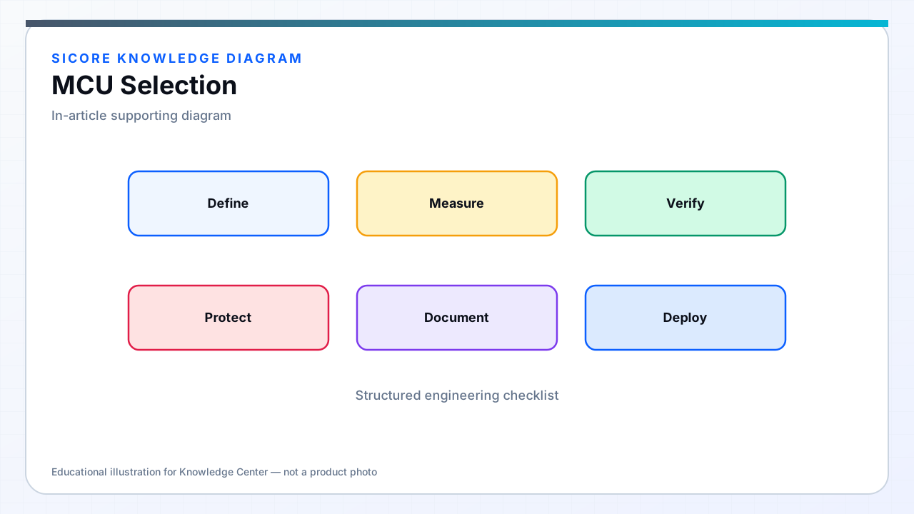
Prototype selection starts from control-loop budget: assign worst-case ISR cycles for PWM, ADC DMA completion, and protection compare units, then add 40–50% margin for communication and diagnostics. Run thermal chamber tests early — elevated die temperature increases wait states and derates effective compute. Final MCU choice is locked only after EMC pre-scan and OTA image size validation on production toolchain settings.