
Wiki article · Collection 05
Autonomous Charging
Engineering reference on Autonomous Charging for wireless power system design, integration, and deployment.
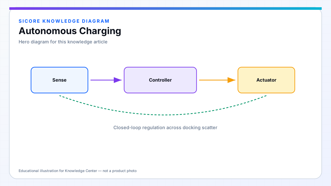
Autonomous charging closes the loop between fleet software and SiCore wireless hardware: the robot navigates to the charge station, aligns within the coil's capture region, establishes digital link, and charges until SOC or schedule criteria are met — then releases and returns to work.
Wireless autonomy removes wear-prone physical contacts and reduces janitorial burden on exposed pins, but it demands reliable pose, communication, and intelligent power control working together.
01System components
- Fleet planner assigning charge tasks from SOC, mission slack, and pad availability.
- Precision docking: SLAM, magnetic tape, QR, or mechanical funnel to repeatable pose.
- Dock localization feedback: alignment score streamed to the robot for micro-correction.
- Charge session state machine: approach → mate → charge → complete → clear field.
02Failure handling
Autonomous systems must degrade gracefully: retry alignment with adjusted approach, reroute to a secondary pad, or alert maintenance if FOD trips repeatedly at one station — often a mechanical issue, not a navigation bug. SiCore logs session abort reasons so root cause is visible across software and hardware teams.
03Throughput design
Autonomy is won or lost in seconds per cycle. Fast load detect, pre-biased frequency tracking, and adaptive power restore charge minutes that navigation spent aligning. Size pad count and charge rates from shift simulation — not from a single-robot demo on an empty floor.